background image

VPanel Window and Functions

12

1. Operation Screen

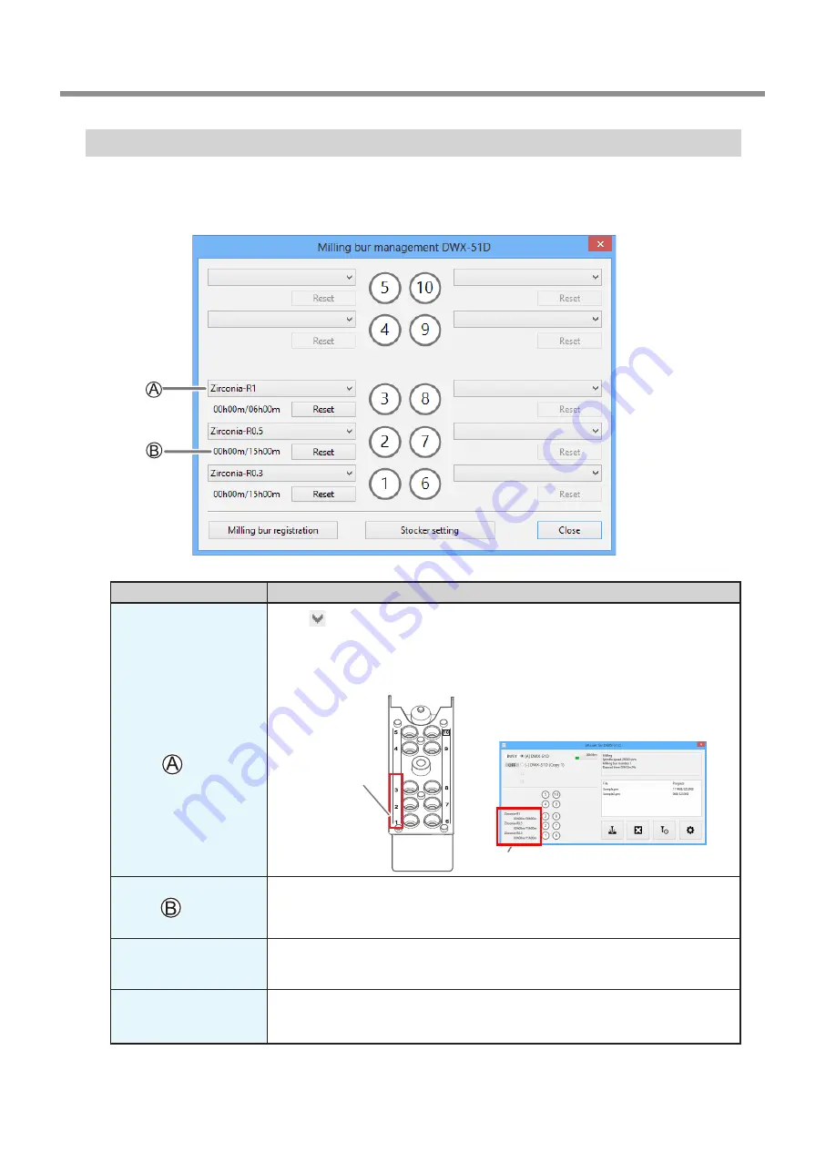
"Milling bur management" Dialog Box

By selecting a milling bur to be used in this dialog box, the work time of the selected milling bur will be recorded automatically.
In addition, when the bur reaches the preset replacement time, a warning message will be displayed. When more than one 
machine is connected, the machine selected in the top window is managed.

Symbol or display

Explanation


Click 

 to display the milling bur for which "Milling bur registration" was performed. 

Numbers 1 through 10 match the stocker numbers on the machine's ATC magazine. The 

information for the selected milling bur will be displayed on the top window.


P. 12""Milling bur management" Dialog Box"

Displays the work time and replacement time of the selected milling bur. When the bur 

reaches the preset replacement time, a warning message will be displayed. The replace-

ment time can be changed from "Milling bur registration." After replacing the milling bur 

with a new one, click "Reset" to set the work time to 0.

Milling bur registration

Here you can register milling burs whose work time you want to manage, or remove burs 

you no longer want to manage. Click here to display the "Milling bur registration" dialog box. 


P. 12""Milling bur management" Dialog Box"

Stocker settings

By setting two stockers as a single set, you can automatically replace milling burs that reach 

their replacement time during milling. Click here to display the "Stocker settings" dialog box.


P. 14""Stocker settings" Dialog Box"

Stocker number

Milling bur information

Summary of Contents for DWX-51D

Page 1: ...l website introducing dental solutions For the latest information regarding this machine including manuals see our special Easy Shape website http www rolandeasyshape com Operation Screen 1 2 Milling 3 Maintenance 4 Troubleshooting User s Manual ...

Page 2: ...illing Burs 19 Preparing Compressed Air Setting the Regulator 19 Starting Milling 20 STEP 1 Mounting the Clamp to the Workpiece 20 STEP 2 Attaching the Milling Bur 26 STEP 3 Outputting Milling Data 27 STEP4 The workpiece from the clamp 29 Automatically Switching Out the Worn Milling Bur Intelligent Tool Control 30 Aborting Output 31 Removing Milling Data in Standby from the Output List 31 3 Mainte...

Page 3: ...ts Do Not Match 53 Installation Trouble 54 Installing the Driver Separately 54 Installing the Softwear and the Electronic Manual Separately 56 Driver Installation Is Impossible 57 Uninstalling the Driver 58 Uninstalling VPanel 59 Responding to Error Messages 60 Thank you very much for purchasing this product To ensure correct and safe usage with a full understanding of this product s performance p...

Page 4: ...Display in the Task Tray 6 Exiting VPanel 6 VPanel Window and Functions 7 Top Window 7 Settings Tab 8 Maintenance Tab 9 Mail Tab 10 Manual correction Dialog Box 11 Milling bur management Dialog Box 12 Milling bur registration Dialog Box 13 Stocker settings Dialog Box 14 Cleaning tool Dialog Box 15 ...

Page 5: ...the Start menu click All Apps or All Programs then Roland DWX 51D Then click VPanel for DWX 51D Windows 8 1 Click on the Start screen and from the Apps screen click the VPanel for DWX 51D icon under Roland DWX 51D VPanel serves as resident software VPanel works as resident software that is constantly working to manage the milling machine send e mails and so on It is recommended to configure the se...

Page 6: ... error has occurred on at least one of the connected milling machines If you hover the mouse pointer over this icon you can check which machine has the error Messages are displayed automatically if an error occurs during milling and in similar situa tions Even after the message disappears if you hover the mouse pointer over this icon the status of each connected machine such as Ready Milling Finis...

Page 7: ...achines are connected Remaining time graph The estimated milling time and a progress bar are displayed Milling bur work time Displays the name of the tool selected in Tool management the current work time and the time when it must be replaced For example 00h01m 06h00m indicates that 00h01m is the work time and 06h00m is the replacement time of the tool Milling machine status Displays the operation...

Page 8: ...ay Initial setting Checked Version VPanel VPanel version Firmware Connected machine s firmware version When more than one machine is connected information for the machine selected in the top window is displayed Override You can adjust the milling speed and the spindle speed This is useful when you want to change the milling speed etc on the fly while monitoring the milling status Overrides are spe...

Page 9: ...x ATC Perform tests maintenance and other tasks related to operation with the ATC magazine The Emergency release button is enabled when the power is turned on while the front cover is open Use this function if initialization cannot be performed because for example the milling bur is caught on the workpiece P 36 Situations Requiring Maintenance P 41 Care and Storage of Detection Pin and Automatic C...

Page 10: ...nnection Check to use a security protected connection SSL Configure the outgoing mail server settings for the e mail address input for the sender s address Use SMTP authentication User name Password Check to use authentication when sending e mails Input the user name and password for authentication Configure the outgoing mail server settings for the e mail address input for the sender s address Cl...

Page 11: ...Zdirections Setthecorrectionvalue while considering the initial moving distance as 100 000 Initial setting 100 000 A axis back side Correct the angle when the A axis is rotated 180 degrees Set the correction value while considering the initial setting as 0 00 degrees Initial setting 0 00 degrees Origin point Correct the origins of the X Y and Z axes Set the correction value while considering the s...

Page 12: ... top window P 12 Milling bur management Dialog Box Displays the work time and replacement time of the selected milling bur When the bur reaches the preset replacement time a warning message will be displayed The replace ment time can be changed from Milling bur registration After replacing the milling bur with a new one click Reset to set the work time to 0 Milling bur registration Here you can re...

Page 13: ...l a function that can be set on the Stocker settings dialog box the work time for the milling bur set as the second milling bur is displayed under Work time 2 P 14 Stocker settings Dialog Box Milling bur info Allows the milling bur name work time and replacement time of the milling bur selected in the list to be edited Click Save to overwrite and save the edited content Because replacement times d...

Page 14: ...ling can be continued for a long time without any loss in milling quality This function is called Intelligent Tool Control Symbol Explanation The stocker combination is displayed here On the screen shown here Pattern 3 has been selected with Intelligent Tool Control is used with the following stocker number combinations 1 and 6 2 and 7 and 3 and 8 Select the stocker combination pattern P 30 Automa...

Page 15: ... dust collector ON OFF For dust collectors with a linking function and connected to the expansion port with a linking cable For details on the dust collector see the DWX 51D Setup Guide Front Movestherotaryaxisunitforward Usethisfunctionwhencleaningtherotaryaxisunit Rear Moves the rotary axis unit to the back Use this function when cleaning the back of the milling area Reverse side Turns the clamp...

Page 16: ...Workpiece Usable Workpieces 19 Preparing a Milling Bur Usable Milling Burs 19 Preparing Compressed Air Setting the Regulator 19 Starting Milling 20 STEP 1 Mounting the Clamp to the Workpiece 20 STEP 2 Attaching the Milling Bur 26 STEP 3 Outputting Milling Data 27 STEP4 The workpiece from the clamp 29 Automatically Switching Out the Worn Milling Bur Intelligent Tool Control 30 Aborting Output 31 Re...

Page 17: ...tatus Light Color Blue The machine is in standby or initializing The light will also turn off if no operation is performed for 30 seconds when in standby causing the machine to sleep White When lit white milling is being performed or has been paused or the front cover is open Also flashes when the dust collector is in standby Yellow When lit yellow an error has occurred and the machine has been pa...

Page 18: ... front cover Switch on the machine s power switch The machine starts initialization When the status light stops flashing and remains steadily lit initialization is complete Switching the Power Off Procedure Switch off the machine s power switch Do not open the front cover during milling ...

Page 19: ...the air pressure adjustment knob slowly and carefully Otherwise the machine may move suddenly posing a risk of injury Pull up on the upper knob The air pressure adjustment knob Slowly turn the upper knob Push down on the upper knob Recommended Set Pressure Shank diameter Ø4 mm Length 40 to 55 mm Pin diameter 6 mm Be sure to configure the regulator to 0 2 MPa or lower Anything higher may result in ...

Page 20: ...en the screws about 3 turns using a torque driver 2 locations Use the included spare screws when a screw is lost or worn Push down on the screw heads to open the workpiece installation section If force is applied in the direction of the back of the machine when you push down on the screw heads the rotary axis may move Forcefully moving the rotary axis by hand is forbidden but there is no problem i...

Page 21: ...piece touches the back of the clamp on the right side Use a torque screwdriver to alternately tighten the screws in the two locations a half turn at a time Tightening only one of the screws at a time may cause the workpiece to break or the screws to become loose during milling For Pin Type Workpieces Ø5 9 0 02 Pin size ...

Page 22: ...er of workpieces that can be attached according to size and their layout Workpiece sizes are limited by the number of workpieces mounted in the machine and the number of mountable workpieces is limited by the size of the workpieces mounted in the machine W 15 mm 15mm W 22 mm L 20mm 50mm L 20mm L 50mm ...

Page 23: ... or worn Push down on the screw heads to open the workpiece installation section If force is applied in the direction of the back of the machine when you push down on the screw heads the rotary axis may move Forcefully moving the rotary axis by hand is forbidden but there is no problem if you have to move it slightly in this manner However do not move the rotary axis by hand multiple times or appl...

Page 24: ...to alternately tighten the screws in the two locations little by little Failing to alternate between the screws whentighteningthemmaycausethepin type material adapter to become tilted Use a torque driver to loosen the screws holding the workpiece in position Use the included spare screws when a screw is lost or worn Align the marks ...

Page 25: ...rial adapter Make sure the recessed portion of the workpiece is oriented downward align the protrusion for pin type material adapter and insert the workpiece all the way in Tighten the screws using a torque driver Align the recessed portion with the protrusion Protrusion ...

Page 26: ...ition Insertthemillingburasinthefigure andmakesurethatbothendsarewithintheareasofthemillingburpositionerholes Secure the mounting screw using the hexagonal screwdriver Set the milling bur in the ATC magazine Insert firmly as far as possible Up to 10 milling burs can be set The stocker numbers are shown on the surface of the magazine OK Not OK Both ends of the milling bur are within the A and B are...

Page 27: ...ow will appear Click Add The Open window will appear Select the milling data and click Open The selected milling data is displayed in the data list of the Output a file window Repeat steps to to output the milling data continuously Verify that the workpiece and the milling bur are set in the machine P 26 STEP 2 Attaching the Milling Bur WARNING Be sure to turn on the dust collector Milling Waste a...

Page 28: ...a list Removing milling data from the data list To remove milling data from the output list select the milling data in the data list and click Remove Adding milling data by dragging and dropping You can add milling data by dragging and dropping data on the window displayed in steps and Do not open the front cover during milling To ensure safety opening the front cover while data is being output wi...

Page 29: ...traight down remove the workpiece from the clamp If you loosen only one screw the workpiece may break If force is applied in the direction of the back of the machine when you push down on the screw heads the rotary axis may move Forcefully moving the rotary axis by hand is forbidden but there is no problem if you have to move it slightly in this manner However do not move the rotary axis by hand m...

Page 30: ... as that in the corresponding stocker Click OK to close the Stocker settings dialog box On the Milling bur management dialog box set the milling burs in the stockers If no milling burs are set in the stockers it will not be possible to switch milling burs automatically P 12 Milling bur management Dialog Box Milling Bur Replacement Time When both milling burs are new The milling bur with the smalle...

Page 31: ...put click OK Click Cancel to not abort the output Removing Milling Data in Standby from the Output List Procedure In the top window of VPanel select the machine to edit from the output list Right click the mouse on the milling data to remove from the output list and click Cancel Only milling data in standby can be removed milling data in the second or following positions from the top of the output...

Page 32: ... after Milling Finishes 34 Periodic Maintenance 36 Situations Requiring Maintenance 36 Replacing Consumable Parts 36 Running In the Spindle Warm up 37 Correcting the Milling Machine 38 Care and Storage of Detection Pin and Automatic Correction Jig 41 Retightening the Collet 41 Care of the Regulator 44 ...

Page 33: ... a fire or explosion WARNING Do not touch the spindle unit or the surrounding areas immediately after milling has ended Doing so may result in burns CAUTION Be careful around the milling tool The milling tool is sharp Broken milling tools are also dangerous To avoid injury exercise caution This machine is a precision device Carry out daily care and maintenance Carefully clean away milling waste Op...

Page 34: ...illing waste in these areas may affect the milling results P 15 Cleaning tool Dialog Box Whenthemachineisinthestandbystate openingthefrontcoverandpressingtheoperationbuttonwillturnonthe dust collector For dust collectors with a linking function and connected to the expansion port with a linking cable For details on the dust collector see the DWX 51D Setup Guide Do not directly touch the inside of ...

Page 35: ...Daily Maintenance 35 3 Maintenance Detection pin Use the included cloth for care to wipe off any dirt from the portion indicated in the figure Part to be wiped ...

Page 36: ...t When the work time of the spindle exceeds 200 hours When water or dust accumulates on the regulator P 44 Care of the Regulator Replacing Consumable Parts A replacement manual is included with purchased products For information on how to perform replacement refer to the replacement instruction manual included with the part Part name Replacement time Guideline Spindle unit When the total work time...

Page 37: ...achine is not used for a prolonged period Before you start using the machine in low room temperature Procedure Close the front cover and turn on the power Show VPanel P 5 Displaying VPanel In the top window of VPanel select the machine to operate Click the radio button to the left of the name of the machine to operate Click The Settings screen will appear Click the Maintenance tab Click Spindle ru...

Page 38: ... in the Z direction etc in cutting result Required Items Detection pin Automatic correction jig Torque driver Cloth for care 1 Install the detection pin Clean off any milling waste around the clamp P 34 Cleaning after Milling Finishes Use the supplied cloth for care to clean the detection pin automatic correction jig and central protrusion on the ATC magazine If any dirt is affixed correction migh...

Page 39: ...in until the protrusions come into contact with the clamp The jig can be attached with either surface facing up If force is applied in the direction of the back of the machine when you push down on the screw heads the rotary axis may move Forcefully moving the rotary axis by hand is forbidden but there is no problem if you have to move it slightly in this manner However do not move the rotary axis...

Page 40: ...e screen is complete Click OK Automatic correction starts Automatic correction is complete once the screen in the figure is displayed Click OK Once automatic correction is complete remove the detection pin and the automatic correction jig To remove the automatic correction jig turn the screws securing the automatic correction jig about 3times and then pull out the automatic correction jig while pu...

Page 41: ...re found Store the detection pin and the automatic correction jig in the storage compartment Retightening the Collet Continuous cutting will cause the collet to become loose making it easy for the milling bur to come off Periodically retighten the collet Recommended Interval for Procedure Once a month or when the total work time of the spindle exceeds 200 hours with slight variation depending on t...

Page 42: ...he detection pin cannot be inserted repeat the opera tion in Tighten the collet with the spanner while holding the detection pin Use the included spanner and keep the detection pin inserted If the detection pin is not inserted the col let may become deformed resulting in lower milling accuracy Tightening is sufficient once the spanner and the tip of the spindle unit shaded portion in the figure to...

Page 43: ...he detection pin and the spanner and close the front cover Click the Maintenance tab Click Close collet The procedure is complete if the spindle unit moves and The operation was completed is displayed The window shown in the figure appears Click OK ...

Page 44: ...f the inside of the bowl becomes dirty remove and wash the bowl Situations Requiring This Work When drainage builds up When the bowl becomes dirty Emptying the Drain Procedure Loosen the lower knob little by little Material may spray out of the drain at this time Use a cloth or the like to catch the spray and keep it from scattering After the drain empties retighten the lower knob Bowl Lower knob ...

Page 45: ...f when compressed air is supplied Procedure Stop the supply of compressed air Loosen the screws about 3 turns in the locations shown in the figure to the left using a torque driver 2 locations Remove the regulator Remove the bowl from the regulator Wash the bowl using a neutral detergent After making sure that the bowl is completely dry retighten the bowl Attach the regulator to the machine WARNIN...

Page 46: ... Area 49 Compressed Air Does Not Come Out 49 Automatic Correction Fails 49 The Milling Bur Management Information was Lost 50 Milling Quality Problems 51 The Milled Surface is Not Attractive 51 There is a Line of Level Difference in the Milling Results 51 Chipping Edges of Milling Products Become Chipped Occurs 51 A Hole Opens in the Milling Results 52 The Dimensions of the Milling Results Do Not ...

Page 47: ...e the cover Are you wearing gloves The operation button will not respond if you are wearing gloves Operate the button with a bare hand VPanel Does Not Recognize the Machine Is the cable connected Make sure that the cables are connected Refer to Setup Guide Connecting the Cables to perform the work Is the driver installed correctly If the connection to the computer is not made in the procedure desc...

Page 48: ...ng data received during initialization or a data cancel will be cancelled Make sure to output mill ing data after confirming that the machine is in the standby status Is the milling data correct Check the milling data Has an error occurred The ERROR LED will flash if an error occurs A de scription of the error is displayed in VPanel P 60 The Computer Shuts Down when Connecting Multiple Machines Ar...

Page 49: ...ttings correctly configured Check the connection Also check whether the regu lator indicates zero If the set pressure of the regula tor is zero compressed air will not be supplied Refer to Setup Guide Preparing the Regulator P 19 Is the knob at the bottom of the regulator open The compressed air will escape if the knob at the bot tom of the regulator is open P 44 Automatic Correction Fails Is the ...

Page 50: ...the machine name printer name changed Milling bur info is saved per machine name printer name Before changing the machine name printer name make sure to record the milling bur info sepa rately Milling bur info can be recovered by returning the machine name printer name to the original name ...

Page 51: ...matic correction If expected results cannot be obtained even after performing automatic correction perform manual correction With manual correction changing the Y value in Origin point may improve the situation P 38 Are the CAM milling settings cor rect Depending on the milling conditions a line of level difference may occur Review the CAM milling condi tions Chipping Edges of Milling Products Bec...

Page 52: ...correction The origin point may become out of position due to prolonged use or relocating the machine which can affect milling results Perform automatic correction If expected results cannot be obtained even after performing automatic correction perform manual correction With manual correction changing the Z value in the direction in Origin point may improve the situation P 38 Are the milling cond...

Page 53: ... milling bur diameter match the CAM settings Is the CAM shrinking percentage setting proper for the workpiece Check the CAM settings Does the settings of the sintering program match the workpiece Check the set temperature of the sintering program to see if it matches the workpiece of the manufac turer used ...

Page 54: ...trol window appears click Allow or Yes and continue with the installation The setup menu screen appears automatically If the driver is already installed uninstall it P 58 Uninstalling the Driver Go to Step if the driver is not installed or if it has been uninstalled Click Custom Install for the DWX 51D Software Click Install for the Windows Driver Windows 10 When the window shown in the figure app...

Page 55: ...ware Package CD Turn on the power to the machine Connect the machine to the computer using the USB cable If connecting more than one unit of this machine to a single computer refer to Setup Guide Connecting Multiple Units For the USB cable use the included cable Do not use a USB hub Connection may not be possible Secure the USB cable with a cable clamp The driver will be installed automatically Im...

Page 56: ...appears click Allow or Yes and continue with the installation The setup menu screen appears automatically Click Custom Install for the DWX 51D Software Click Install for VPanel or Manual Follow the on screen instructions to proceed with the installation When the installation finishes click on the setup menu Remove the Roland Software Package CD ROM With this machine you can also install the driver...

Page 57: ...double click it Under the selected item click the name of the model you are using or Unknown device 8 Go to the Action menu and click Uninstall 9 In the Confirm Device Uninstall window click OK Close Device Manager 10 Detach the USB cable from the computer and then restart Windows 11 Uninstall the driver Carry out the steps from step 3 on page 58 Uninstalling the Driver Windows 10 8 1 to uninstall...

Page 58: ...ice When using the CD specify the folder as shown below This is assuming your CD drive is the D drive D Drivers WIN8X64 64 bit versions D Drivers WIN8X86 32 bit versions If you re not using the CD go to our special Easy Shape website http www rolandeasyshape com and download the driver for the machine you want to remove and then specify the folder where you want to extract the downloaded file Wind...

Page 59: ...nel andthenclick Uninstallaprogram or ProgramsandFeatures 3 Select Roland VPanel for DWX 51D and click Uninstall 4 Follow the on screen instructions to uninstall Windows 7 1 Exit VPanel Right click VPanel icon in the task tray and select Exit 2 From the Start menu click Control Panel and then click Uninstall a program or Programs and Features 3 Select Roland VPanel for DWX 51D and click Uninstall ...

Page 60: ...s opened during spindle rotation For safety the machine comes to an emergency stop if the front cover is openedwhilethespindle is rotating To continue milling Press the operation button on the built in panel to resume milling To stop milling Press and hold the operation button on the built in panel Do not open the front cover while the spindle is rotating Doing so may affect the milling results 10...

Page 61: ...let The milling conditions may be excessively strict 1 Press and hold the operation button on the built in panel This will clear the error 2 Review the CAM settings and the shape specified in the CAD data The collet may be worn out If the error occurs again even after you perform the above operations the collet may have worn out leading to a decrease in its retention capabilities Replace the colle...

Page 62: ...asons The milling bur is worn A workpiece that can not be milled by the ma chine is being used The milling conditions are too strict 1 Turn off the power 2 Check the milling bur the workpiece and the CAM settings as well as the shape specified in the CAD data 3 Allow the machine to rest for some time be fore turning the power on because the motor may have overheated 102A 0000 T h e s p i n d l e e...

Page 63: ... short or if the angle of the A axis and B axis are too large the milling bur may not reach the milling position in the Z direction 1 Press and hold the operation button on the built in panel This will clear the error 2 Check the milling bur length and the position of the milling bur holder P 26 STEP 2 Attaching the Milling Bur 3 Review the CAM settings and decrease the angles of the A axis and th...

Page 64: ...R2 160616 FA01061 ...

Reviews: