


9/12
© 2021 ROHM Co., Ltd.
No. 63UG103E Rev.001
2021.2
User’s Guide
BD16950EFV-EVK-001
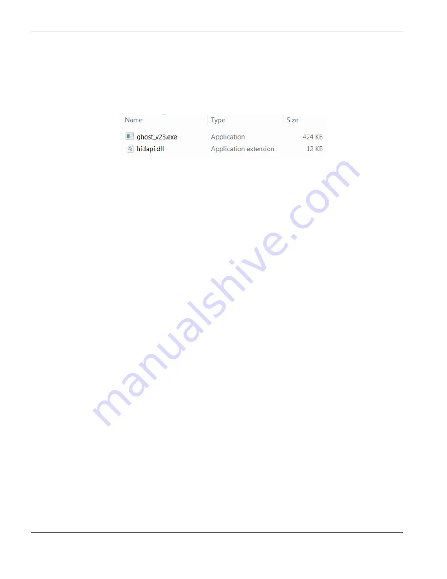
4.2 Software
The BD16950EFV-C software user interface consists of an .exe and .dll file, which have to be copied in one folder of your Windows
PC. Please check with your local ROHM sales office or ROHM customer support system to have the latest software version.
Since the GUI is designed as Human Interface Device (HID), no driver installation will be required.
After plugging in the evaluation board with the USB cable to the PC it will automatically be recognized by Windows and show as
“GHOST USB Interface” in “Devices and Printers”.
Figure 6: User Interface Software Files
NOTE: The evaluation board should be connected by USB cable to the PC before starting the software.
Then the software can be started by double clicking the “.exe” file.
In case the USB Cable is not connected or recognized by Windows, the GUI will report so (Figure 8).
In case the USB Cable is connected but not recognized, disconnect the USB cable and reconnect after 5-6 seconds.
GUI Description:
•
PWM sliders:
Set the duty cycle of the two PWM input signals which connect to BD16950EFV-C.
•
RESET button:
RES(H): High pin level, RES(L): Low pin level. Typically not required to change.
•
SEL button:
SEL(H): High pin level. Will only switch to low when SPI Read / Write. SEL(L): Constantly low.
•
SET pull-down menu:
Can select some pre-defined register settings. (Table 4, Table 5)
When the menu is selected, reset chip and set registers on table 4. Then enable “Enable Register” to drive motor.
•
CMD pull-
down menu: Select the register by address and name to apply your desired settings. Only BD16950EFV-C specific
commands can be sent. OR use “raw” mode to send/receive general commands to the SPI interface.
•
WR button:
Write the configured Bits to the selected register.
•
RD button:
Read the selected register.
Use the buttons to the left of the “WR” button to set the individual Bits of the selected register. The resulting binary word is shown as
HEX value.
The following procedure is recommended in particular when operating the first time in a new application:
1. Set PWM1 slider to 100 and PWM2 slider to 0
(PWM1:”100” is PWM duty 0 %, PWM2:”0” is PWM duty 0 %)
2. Configure registers 02h-08h according to your application.
3. Enable the IC, charge pump and output drivers in register 01h
4. Increase PWM duty cycle (only applicable if your configured mode of operation uses PWM) and monitor load current and
EVK temperature.


