


Safety Instructions - Informaciones de seguridad
1171.0300.32 E/Esp-2
Informaciones de seguridad para aparatos con
telepiés
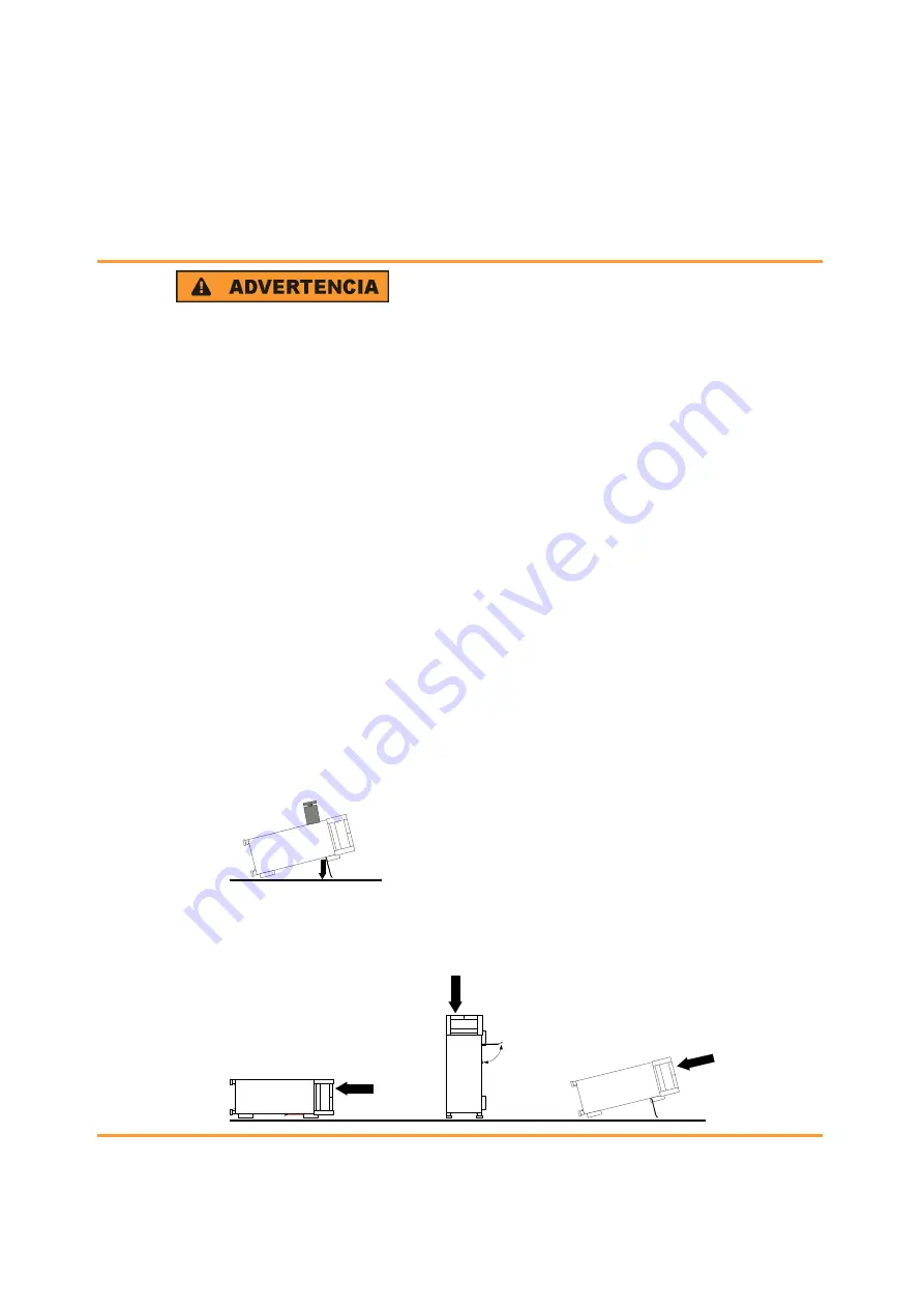
Peligro de heridas
Los telepiés pueden doblarse hacia adentro si no han sido desdobla-
dos por completo o si el aparato es movido. Los telepiés pueden rom-
perse si son sobrecargados.
Doblar los telepiés por completo hacia afuera o hacia adentro. De esta
manera se puede asegurar la estabilidad del aparato y a la vez la segu-
ridad de las personas.
No mover nunca el aparato con los telepiés desdoblados, para evitar
heridas.
El peso total equilibrado (peso própio más el de los aparatos posicio-
nados sobre este) ejercido sobre los telepiés no deberá exceder a los
500 N.
Posicionar el aparato sobre una superficie estable. Los aparatos pues-
tos encima de esté deben estar asegurados para que no resbalen (por
ejemplo fijando los piés del aparato en el listón del marco de delante
arriba).
Por favor no manipulen debajo del aparato y no pongan nada debajo
de este cuando esté posicionado sobre los telepiés desdoblados, ya
que si no pueden originarse heridas o daños en objetos.
<500 N
El aparato puede ser puesto en funcionamiento en cualquiera de las
posiciones aquí descritas.
深圳德标仪器
135-1095-0799


