background image

38

Important Notes

38

Important Notes

1  Important Notes

1.1 Symbols 


    (1) 

(2) 

(3) 

(4)


   (5) 

  (6) 

  (7)

Symbol 1:  

Caution, general danger zone – 


Refer to product documentation

Symbol 2:  

Risk of electric shock 

Symbol 3:  

Ground

Symbol 4:  

PE terminal

Symbol 5:  

ON (supply voltage)

Symbol 6:  

OFF (supply voltage)

Symbol 7:  

Ground terminal

1.2 Unpacking

While unpacking, check the package contents for com-
pleteness (measuring instrument, power cable, product 
CD, possibly optional accessories). After unpacking, check 
the instrument for mechanical damage occurred during 
transport and for loose parts inside. In case of transport 
damage, please inform the supplier immediately. The 
instrument must not be operated in this case.

1.3  Setting Up the Instrument

As shown in the illustrations, small hinges on the bottom 
stands can be folded out to set up the instrument in a 
slightly inclined position. Please make sure that the stands 
are completely folded out to ensure a stable position.

The instrument must be positioned in a manner that allows 
the user to disconnect the unit from the mains at any time 
and without restrictions.    

1.4 Safety

This instrument was built in compliance with DIN EN 
61010-1 (VDE 0411 part 1), safety regulations for electrical 
measuring instruments, control units and Iaboratory equip-
ment. It has been tested and shipped from the plant in safe 
condition. It is in compliance with the regulations of the 
European standard EN 61010-1 and the international stan-
dard IEC 61010-1. To maintain this condition and to ensure 
safe operation, the user must observe all instructions and 
warnings given in this operating manual. Casing, chas-
sis and all measuring ports are connected to a protective 

Fig. 1.1: Operating positions

earth conductor. The instrument is designed in compliance 
with the regulations of protection class I. 

For safety reasons, the instrument may only be operated 
with authorized safety sockets. The power cord must be 
plugged in before signal circuits may be connected. Never 
use the product if the power cable is damaged. Check 
regularly if the power cables are in perfect condition. 
Choose suitable protective measures and installation types 
to ensure that the power cord cannot be damaged and 
that no harm is caused by tripping hazards or from electric 
shock, for instance.

If it is assumed that a safe operation is no longer possible, 
the instrument must be shut down and secured against 
any unintended operation. 

Safe operation can no longer be assumed:

 ❙If the measuring instrument shows visible damage 
 ❙If the measuring instrument includes loose parts 
 ❙If the measuring instrument no longer functions properly
 ❙After an extended period of storage under unfavorable 

conditions (e.g. outdoors or in damp rooms)

 ❙After rough handling during transport (e.g. packaging 

that does not meet the minimum requirements by post 
office, railway or forwarding agency). 

Prior to switching on the product, it must be ensured that 
the nominal voltage setting on the product matches the 
nominal voltage of the AC supply network. If it is neces-
sary to set a different voltage, the power fuse of the pro-
duct may have to be changed accordingly.

1.5  Intended Operation  

The measuring instrument is intended only for use by 
personnel familiar with the potential risks of measuring 
electrical quantities. For safety reasons, the measuring 
instrument may only be connected to properly installed 
safety socket outlets. Separating the grounds is prohibited. 
The power plug must be inserted before signal circuits 
may be connected.     

It is prohibited to disconnect the earthed protective 

connection inside or outside the instrument!

Exceeding the Low Voltage Protection! 
For the series connection of all output voltages, it is pos-
sible to exceed the low voltage protection of 42 V. Please 
note that in this case any contact with live components 

is life-threatening. It is assumed that only qualified and 

trained personnel service the power supplies and the 
connected loads.

Use the measuring instrument only with original ROHDE & 
SCHWARZ measuring equipment, measuring cables and power 
cord. Never use inadequately measured power cords. Before 
each measurement, measuring cables must be inspected for 
damage and replaced if necessary. Damaged or worn compo-
nents can damage the instrument or cause injury.

www.allice.de

Allice Messtechnik GmbH

Summary of Contents for 3593.1006.02

Page 1: ...5800451102 HMC804x Power Supply Benutzerhanduch Benutzerhandbuch User Manual Version 05 www allice de Allice Messtechnik GmbH ...

Page 2: ...www allice de Allice Messtechnik GmbH ...

Page 3: ...71 Appendix 71 Appendix www allice de Allice Messtechnik GmbH ...

Page 4: ...Leitungslänge vorschreibt dürfen Datenleitungen Eingang Ausgang Signal Steuerung eine Länge von 3m nicht über schreiten und sich nicht außerhalb von Gebäuden befinden Ist an einem Geräteinterface der Anschluss mehrerer Schnitt stellenkabel möglich so darf jeweils nur eines angeschlossen sein Bei Datenleitungen ist generell auf doppelt abgeschirm tes Verbindungskabel zu achten 2 Signalleitungen Mes...

Page 5: ... Überlastschutz OPP 15 5 5 Tracking Funktion 15 5 6 EasyArb Editor 16 5 6 1 Datenformatbeispiel einer Arbitrarydatei 17 5 6 2 Beispiel für eine Arbitrarykurve mit der HMExplorer Software 17 6 Erweiterte Bedienfunktionen 18 6 1 Terminal Anschluss 18 6 1 1 19 Rack Einbausatz 18 6 2 Analog In 18 6 2 1 Analog In Beispiel 19 6 3 Sequencing 19 6 4 Externer Trigger 20 6 5 EasyRamp 20 6 6 Parallel und Ser...

Page 6: ...romkreise angeschlossen werden Benutzen Sie das Produkt niemals wenn das Netzkabel beschädigt ist Überprüfen Sie regel mäßig den einwandfreien Zustand der Netzkabel Stellen Sie durch geeignete Schutzmaßnahmen und Verlegearten sicher dass das Netzkabel nicht beschädigt werden kann und niemand z B durch Stolperfallen oder elektrischen Schlag zu Schaden kommen kann Wenn anzunehmen ist dass ein gefahr...

Page 7: ...it von mindestens 30Minuten und bei einer Umgebungstemperatur von 23 C Toleranz 2 C Werte ohne Toleranzangabe sind Richtwerte eines durchschnittli chen Gerätes Die im R S HMC804x erzeugte Wärme wird durch einen temperaturgeregelten Lüfter nach außen geführt Jeder Kanal besitzt einen eigenen Temperatursensor welcher die Wärmeentwicklung im Gerät überprüft und dement sprechend die Lüfterdrehzahl ste...

Page 8: ...ng ist von außen zugänglich Netzstecker Buchse und Sicherungshalter bilden eine Die Außenseite des Messgerätes sollte regelmäßig mit einem weichen nicht fasernden Staubtuch gereinigt werden Bevor Sie das Messgerät reinigen stellen Sie bitte sicher dass es ausgeschaltet und von allen Spannungsversorgungen getrennt ist z B speisendes Netz oder Batterie Keine Teile des Gerätes dürfen mit chemischen R...

Page 9: ...n besteht Explosionsgefahr Zel len oder Batterien nur durch den entsprechenden Typ ersetzen um die Sicherheit des Produkts zu erhalten 8 Zellen oder Batterien müssen wieder verwertet werden und dürfen nicht in den Restmüll gelangen Akkumula toren oder Batterien die Blei Quecksilber oder Cad mium enthalten sind Sonderabfall Beachten Sie hierzu die landesspezifischen Entsorgungs und Recycling Bestim...

Page 10: ...auf allgemeine Geräteeinstellungen 6 HELP Integrierte Hilfeanzeige 7 SHIFT Umschalttaste zum Aktivieren des Ziffern blocks 8 Universaldrehgeber mit Pfeiltasten Einstellen der Sollwerte Editiertasten 9 POWER Ein Aus für Standby Modus 10 USB Anschluss USB Anschluss zum Abspeichern von Parametern 11 CH1 4mm Sicherheitsbuchsen Ausgang Kanal 1 0V bis 32V 3A 12 CH2 4mm Sicherheitsbuchsen Ausgang Kanal 2...

Page 11: ...cks 8 Universaldrehgeber mit Pfeiltasten Einstellen der Sollwerte Editiertasten 9 CH1 4mm Sicherheitsbuchsen Ausgang Kanal 1 0V bis 32V 5A 50W max 10 CH2 4mm Sicherheitsbuchsen Ausgang Kanal 2 0V bis 32V 5A 50W max Geräterückseite HMC8042 Siehe Geräterückseite HMC8043 1 Display Farb Display 320 x 240 Pixel 2 Interaktive Softmenütasten Direkte Erreichbarkeit aller relvanten Funktionen 3 Funktionsta...

Page 12: ...oll die Spannung eines Kanals mit Hilfe des Drehgebers einge stellt werden so wird die Taste VOLTAGE betätigt und mit den Pfeiltasten die zu verändernde Dezimalstelle gewählt Durch Rechtsdrehen des Drehgebers wird der Sollwert der Ausgangsspannung erhöht durch Linksdrehen verringert Das Gleiche gilt für die Einstellung des Stromwertes Je nach Gerätetyp stehen bis zu 3 galvanisch getrennte und somi...

Page 13: ...esen Datenarten lassen sich Bildschirmfotos nur auf einem angeschlossenen USB Stick abspeichern Geräte einstellungen lassen sich sowohl auf einem USB Stick als auch intern in nichtflüchtigen Speichern im Gerät ablegen Durch Druck auf die Taste SAVE RECALL wird das Spei chern und Laden Menü geöffnet Mit dem Softmenü DE VICE SETTINGS können Geräteeinstellungen geladen oder gespeichert werden Zum Spe...

Page 14: ...t benutzerdefinierten Einstellungen belegt werden Hierzu wird die jeweilige Taste lang gedrückt Gespeichert Abb 4 2 Nummerische Tastatur mit Funktionstasten werden nicht nur Strom und Spannungswert sondern alle kanalspezifischen Einstellungen wie z B FUSE OVP etc Zum Laden der Einstellungen werden die Tasten USER1 oder USER2 kurz betätigt Um die Zerstörung einer extern angeschlossenen Schaltung du...

Page 15: ...ivierten Kanals je nach Modus in grün CV Konstantspannungsbetrieb oder rot CC Konstantstrombetrieb Ist der Ausgang MASTER ON OFF deaktiviert so werden die Werte auf dem Display in gelb angezeigt 1 0 3 I V 10 32 0 Abb 4 4 R S HMC8043 Leistungshyperbel Abb 4 5 Aktivierung von Kanal 1 und Kanal 2 mit MASTER ON 4 7 LIVE Mode Zusätzlich zu den bereits erwähnten Einstellungsmöglich keiten über das Kanal...

Page 16: ...wahltaste CH1 CH2 CH3 und der Softmenütaste FUSE gesetzt oder gelöscht wer den Mittels Softmenütaste CHANNEL kann der jeweilige Kanal ausgewählt und mit der Softmenütaste ACTIVATE die Sicherung des entsprechenden Kanals aktiviert bzw deaktiviert werden Wurde für einen oder mehrere Kanäle die elektronische Sicherung aktiviert so wird im Display ein Sicherungszeichen angezeigt Wurde die elektronisch...

Page 17: ...ion ist nicht im normalen Funktionsmodus aktiv ausgewählten Kanal aktiviert ON bzw deaktiviert OFF Steigt die Spannung über den voreingestellten Wert UMAX wird der jeweilige Kanal abgeschaltet und somit der Verbraucher geschützt Wurde der Überspannungsschutz ausgelöst so blinkt im Display OVP 5 4 Überlastschutz OPP Der Überlastschutz kann für jeden Kanal individuell einge stellt werden Softmenütas...

Page 18: ...er bestätigt Die einzelnen Spalten oder Zeilen werden mit den Pfeiltasten ausgewählt Zusätzlich gibt es die Möglichkeit die erstellten Punkte zu interpolie ren INTP Y oder nicht INTP N Die TRACK Funktion kann ausschließlich in der lokalen Betriebs art Frontbedienung verwendet werden Via Remote Betrieb SCPI Kommandos ist die TRACK Funktion nicht nutzbar da laut SCPI Standard jeder Kanal als Instrum...

Page 19: ...itere Möglichkeit zur Erstellung einer Arbitrary kurve ist das Arbitrary Softwaremodul der HMExplorer Software Hier kann Punkt für Punkt mit dem Editor eine Kurve erstellt werden Einzelne Punkte können mit der Funktion oder eingefügt oder gelöscht werden Mit der Funktion INTERPOLATION können zusätzlich die defi nierten Arbitrarypunkte interpoliert ausgegeben werden Abb 5 9 Arbitrary Editor Beispie...

Page 20: ...factured in CzechRepublic F 5013569 MC 253564 Abb 6 2 Anschlussbeispiel einer Steckklemmleiste 6 2 Analog In Auf der Geräterückseite befinden sich die Anschlüsse für analoge Steuersignale siehe Kap 6 1 Terminal Anschluss Mit dem R S HMC804x ist es möglich wahlweise über ein Spannungs 0V bis 10V oder Stromsignal 4mA bis 20mA die Ausgangsspannungen des Netzteils zu steu ern Beide Signale dürfen nich...

Page 21: ...ON OFF automatisch mit einem einstellbaren Zeitversatz nacheinander zugeschaltet Ebenso ist ein zeit gleiches Ein bzw Ausschalten aller Kanäle möglich Der Zeitversatz zwischen den einzelnen Kanälen kann mit der Die Analog In Funktion kann nicht gleichzeitig mit Sequencing EasyRamp oder der Arbitrary Funktion genutzt werden Abb 6 4 Analog In Beispiel Sequencing kann nicht gleichzeitig mit der Arbit...

Page 22: ... Erhöhung von Ausgangsspannung strom lassen sich die Kanäle in Reihen bzw Parallelschaltung betreiben Die Ausgangsspannungen welche kombiniert werden sollen sind in der Regel voneinander unabhängig Dabei können die Ausgänge eines oder mehrerer Netzgeräte miteinander verbunden werden 6 6 1 Serienbetrieb Bei dieser Art von Verschaltung addieren sich die einzelnen Ausgangsspannungen Es fließt durch a...

Page 23: ...V 2 A 16 V 2 A Abb 6 9 Beispiel für Parallelbetrieb 16 V 4 A Eine negative Spannung kann nur durch eine Verschaltung von zwei Kanälen erreicht werden Ein negativer Spannungsbereich mit nur einem Kanal ist nicht möglich Durch eine leichte Spannungserhöhung kann die Lastverteilung beeinflusst werden Wird bei einem Kanal die Spannung um z B 50mV höher gewählt bei einem Satz identischer Kabel wird zun...

Page 24: ...e Anzahl der Messwertaufzeichnungen eingestellt werden Wird z B ein Interval von 2s und ein Count von 5 eingestellt so werden 5 Messwerte im Ab stand von 2s aufgezeichnet Ist die Funktion T aktiviert so kann mit der Softmenütaste TIME die Aufzeichnungs dauer der Messwerte mit dem Drehgeber eingestellt werden 7 1 Datenformatbeispiel einer Logging Datei Device R S HMC8043 Device Name Device under te...

Page 25: ...oftmenütaste STORAGE kann ein möglicher Speicherort Internal oder Front ausgewählt werden auf dem die Geräteeinstellungen gespeichert werden sollen Nach Auswahl des entsprechenden Spei cherortes und betätigen der Softmenütaste ACCEPT öffnet sich der Dateisystemmanager Der Dateiname FILE NAME kann an die jeweilige Einstellung angepasst bzw verändert werden SET ist die Standardbezeichnung Über die S...

Page 26: ...ann ein Screenshot je nach gewählter Menü Einstellung z B auf einem angeschlos senen USB Stick gespeichert werden 9 Allgemeine Einstellungen Wichtige Grundeinstellungen wie allgemeine oder Schnitt stellen Einstellungen können mittels SETUP Taste einge stellt werden Mit der Taste gelangt man eine Ebene zurück 9 1 Update Gerätefirmware Die Firmware ist in eine ZIP Datei gepackt Ist die ZIP Datei her...

Page 27: ...Softmenü DISPLAY und der Softmenütaste BACKLIGHT kann die Intensität des Bildschirmes mit dem Drehgeber von 10 bis 100 variiert werden Mittels Softmenütaste CONTRAST kann der Kontrast und mit BRIGHTNESS die Helligkeit des Bildschirms von 10 bis 100 eingestellt werden Der jeweilige Softmenüpunkt ist aktiv wenn dieser gelb markiert ist 9 3 5 Tastenhelligkeit KEY Mit der Softmenütaste KEY BRIGHT kann...

Page 28: ...bitrarykurven zu erstel len 10 2 USB TMC Die moderne Alternative zum virtuellen COM Port VCP ist die Ansteuerung mit Hilfe der USB TMC Klasse TMC steht dabei für die Test Measurement Class und bedeutet dass bei installierten VISA Treibern das angeschlossene Messgerät ohne spezielle Windows Treiber erkannt wird und in den entsprechenden Umgebungen direkt verwen det werden kann Der Aufbau des TMC Mo...

Page 29: ...en Installationsanweisungen Hier beispielhaft für NI VISA 5 4 1 Starten Sie die Installation mit Weiter und folgen Sie den Installationsanweisungen In diesem Schritt wählen Sie bitte unter NI VISA xxx Alle Anwendungen lokal installieren aus Abb 10 4 NI VISA 5 4 1 Abb 10 5 NI VISA Installationsanweisung Nach der erfolgreichen Installation der NI VISA Treiber können Sie nun Ihr R S HMC804x Netzgerät...

Page 30: ...ntiert dabei eine Binärzahl von 8 Bit IP Adressen werden in öffentliche und private Adressbe reiche aufgeteilt Öffentliche IP Adressen werden durch das Internet geroutet und können von einem Internet Service Provider ISP bereitgestellt werden Netzelemente die eine öffentliche IP Adresse besitzen können über das Internet direkt erreicht werden bzw können über das Internet Daten direkt austauschen P...

Page 31: ...5 255 255 Reserviert für Multicast Anwendungen E 240 0 0 1 255 255 255 255 Reserviert für spezielle Anwendungen Tab 10 2 Klassen von IP Adressen Adressbereich Subnetzmaske n CIDR Schreibweise Anzahl möglicher Hostadressen 10 0 0 0 10 255 255 255 255 0 0 0 10 0 0 0 8 224 2 16 777 214 172 16 0 0 172 31 255 255 255 240 0 0 172 16 0 0 12 220 2 1 048 574 192 168 0 0 192 168 255 255 255 255 0 0 255 255 ...

Page 32: ...B die Vorteile von Ethernet mit der Einfachheit und Benutzerfreundlichkeit von GPIB verbinden Das R S HMC804x ist LXI zertifiziert und entspricht der Version 1 4 LXI Core 2011 Erweiterte Funktionen wer den nicht unterstützt Zentraler Bestandteil einer LXI Zertifizierung sind IVI Gerätetreiber Interchangeable Virtual Instrument Hier werden sog IVI net Treiber zur Verfügung gestellt die auf dem NET ...

Page 33: ... durch ein R S HMC804x Modell ersetzt werden Die Einstellungen der notwendigen Parameter erfolgt im R S HMC804x nachdem IEEE488 als Schnittstelle ausgewählt und die Softmenütaste PARAMETER gedrückt wurde Die optionale IEEE 488 Schnittstelle GPIB kann nur ab Werk eingebaut werden da hierzu das Gerät geöffnet und das Garantie siegel verletzt werden muss Das Ethernet Passwort kann nur über das HMC Et...

Page 34: ...5 1mA I 100mA HMC8042 0 05 4mA typ 0 1 2mA I 100mA HMC8041 0 15 10mA typ 0 2 4mA I 100mA Auflösung Spannung alle Modelle 1mV Strom HMC8043 HMC8042 0 1mA I 1A 1mA I 1A HMC8041 0 5mA I 1A 1mA I 1A Spannung gegen Erde 250VDC Gegenspannung max 33V Verpolte Spannung max 0 4V Max zulässiger Strom bei verpolter Spannung 3A Weiterführende Spezifikationen Frontanschlüsse 4mm Sicherheitsbuchsen Rückseitige ...

Page 35: ...mware Update Menü 24 Abb 9 2 Setup Menü 25 Abb 9 3 Geräteinformation 25 Abb 9 4 Eingabe des Gerätenamens 25 Abb 10 1 Geräterückseite 26 Abb 10 2 USB VCP Einstellung 26 Abb 10 4 NI VISA 5 4 1 27 Abb 10 5 NI VISA Installationsanweisung 27 Abb 10 6 NI VISA Anwendung lokal installieren 27 Abb 10 7 Setup Menü 27 Abb 10 8 Schnittstellen Menü 27 Abb 10 9 TMC Anzeige auf dem Display 28 Abb 10 10 Gerätetre...

Page 36: ...G Geräteeinstellungen 23 Gesamtstrom 21 Gewährleistung 5 GPIB 31 Grenzwerte 7 11 16 I Interpolation 17 K Key Fallback Time 12 14 16 26 Konstantspannungsbetrieb 13 14 Konstantstrombetrieb 13 14 20 L LIVE Modus 13 Logging 8 9 11 20 22 34 M Messintervall 22 Messkategorie 6 Messwerterfassung 22 P Produktentsorgung 7 R Reparatur 5 6 Repetierrate 16 S Schutzklasse 4 Sense 9 18 Sequencing 11 16 19 20 Ser...

Page 37: ...35 Anhang 35 Anhang www allice de Allice Messtechnik GmbH ...

Page 38: ...5800451102 HMC804x Power Supply User Manual Benutzerhandbuch User Manual Version 05 www allice de Allice Messtechnik GmbH ...

Page 39: ...www allice de Allice Messtechnik GmbH ...

Page 40: ...71 Appendix 71 Appendix www allice de Allice Messtechnik GmbH ...

Page 41: ...ess the manual prescribes an even shorter maximum cable length data cables input output signal control may not exceed a length of 3m and may not be used outside of buildings If the instrument interface includes multiple ports for inter face cables only one cable at a time may be connected Generally interconnections require double shielded con necting cables 2 Signal Cables In general measuring cab...

Page 42: ...8 5 2 2 Fuse Delay 49 5 3 Over Voltage Protection OVP 49 5 4 Overload Protection OPP 49 5 5 Tracking Function 49 5 6 EasyArb Editor 50 5 6 1 Data Format Example for an Arbitrary File 51 5 6 2 Example of an Arbitrary Waveform 51 6 Advanced Operating Functions 52 6 1 Terminal Connector 52 6 1 1 19 Rack Mount Kit 52 6 2 Analog In 52 6 2 1 Analog In Example 52 6 3 Sequencing 53 6 4 External Trigger 54...

Page 43: ...les are in perfect condition Choose suitable protective measures and installation types to ensure that the power cord cannot be damaged and that no harm is caused by tripping hazards or from electric shock for instance If it is assumed that a safe operation is no longer possible the instrument must be shut down and secured against any unintended operation Safe operation can no longer be assumed If...

Page 44: ...rature sensor which checks the heat generation in the instrument and controls the fan speed However it is necessary to ensure that there is sufficient space on both instrument sides for the heat exchange If the temperature inside the instrument still increases to more than 80 C a channel specific overheat protec tion intervenes Affected outputs will automatically be switched off 1 7 Maintenance Th...

Page 45: ...ching is not intended The input line fuse is accessible externally Power socket and fuse holder form a single unit You need to first disconnect the power cord from the con nector before you can safely replace the fuse as long as the fuse holder is undamaged Next the fuse holder must be pried out using a screwdriver The starting point is a slot next to the contacts Then the fuse can be forced out o...

Page 46: ... or batteries only with the matching type in order to ensure the safety of the product 8 Cells and batteries must be recycled and kept separate from residual waste Cells and batteries must be recycled and kept separate from residual waste Rechargeable batteries and normal batteries that contain lead mercury or cadmium are hazardous waste Observe the national regulations regarding waste disposal an...

Page 47: ...the HMC8043 2 Description of the Operating Elements Front panel of HMC8043 1 Display Color display 320 x 240 pixel 2 Interactive soft menu keys All relevant functions are directly accessible 3 Function keys To be used as numeric keypad in SHIFT function CH1 Settings for channel 1 CH2 Settings for channel 2 CH3 Settings for channel 3 CH1 ON OFF Activating Deactivating channel 1 CH2 ON OFF Activatin...

Page 48: ...y 7 SHIFT Shift key to activate the numeric keypad 8 Universal knob with arrow keys Setting desired values edit keys 9 CH1 4mm safety sockets Outputs channel 1 0V to 32V 5A 50W max 10 CH2 4mm safety sockets Outputs channel 2 0V to 32V 5A 50W max Back Panel of HMC8042 Refer to back panel of HMC8043 1 Display Color display 320 x 240 pixel 2 Interactive soft menu keys All relevant functions are direc...

Page 49: ...E key must be activated so you can select the desired decimal point via arrow keys The nominal value of the output voltage is increased by turning the knob to the right and it is decreased by turning it to the left The same applies to the value selection of the current Depending on the instrument type up to 3 galvanically isolated and hence combinable channels are available The R S HMC8043 has thr...

Page 50: ...nstrument settings Select the storage location and the file name then press the soft menu key SAVE to save the current instrument settings This file may be reloaded at a later time The menu item DEFAULT SETTINGS in the main menu also allows you to load the factory default settings 4 Selecting the Parameters 4 1 Description of the Display The display values of the R S HMC8041 differs from the R S H...

Page 51: ...ER2 key will load the settings To avoid destruction of an externally con nected circuit due to operating errors the output will be deactivated before changing the output voltage This must be reactivated manually Fig 4 2 Numeric keypad with function keys 4 2 2 Knob with Arrow Keys You can also use the knob to enter the parameter values The input will be modified gradually and the respective input p...

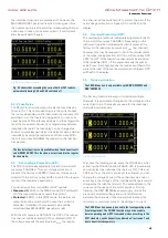
Page 52: ...the display values will be displayed in yellow 4 7 LIVE Mode In addition to the already mentioned settings options in the channel short menu the LIVE mode is also available The LIVE mode allows you to select the current and voltage values for the respective channel directly on the display Press the knob for an extended period to activate the LIVE mode The instrument automatically switches to the v...

Page 53: ... constant voltage mode to red CC constant current mode 5 2 Fuse A current limit indicates that only a specific maximum current Imax can flow Prior to operating an experimental circuit this maximum value will be selected at the power supply and if the fuse is triggered the corresponding channel will be deactivated The intent is to prevent dam age to the experimental circuit in case an error occurs ...

Page 54: ...ed MASTER ON This function is not activated in the regular function mode tive channel will be switched off to protect the load If the over voltage protection is tripped OVP will flash in the display 5 4 Overload Protection OPP The overload protection is individually adjustable for each channel soft menu key CHANNEL Depending on the instrument type the overload protection is preset at the factory t...

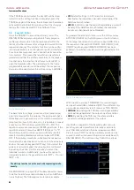
Page 55: ...pad SHIFT key If you select the values via numeric keypad the values will be confirmed by pushing the knob Use the arrow key to select the individual columns Additionally you have the option to interpolate between the generated points INTP Y or not INTP N Use END BEHAV on page 2 2 of the EasyArb editor menu to define the arbitrary endpoint behavior when ARB func tion is finished The following menu...

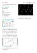
Page 56: ...y use of the editor You can add or delete individual points by using the or function With the function INTERPOLATION the defined arbitrary points can be output interpolated Once all arbitrary points have been created the created signal can be transferred to the instrument via interface by using the menu item TRANSFER The menu TRANSFER opens and allows you to select the respective R S HMC channel a...

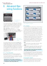
Page 57: ...e for 19 rack mount The Analog In function can not be used with sequencing Easy Ramp or arbitrary function simultaneously 6 Advanced Ope rating Functions 6 1 Terminal Connector The terminal connector on the back panel of the instru ment allows you to execute the voltages currents of all channels including SENSE The 16 pole terminal block includes the following connectors for each channel P corresp...

Page 58: ...owing sequencing start options are available Starting sequencing with MASTER ON Select the corresponding channels in the Sequencing menu ACT CH1 ACT CH2 ACT CH3 activate the sequencing via soft menu key ACTIVATE and then activate the channels via channel key CH1 ON OFF CH2 ON OFF or CH3 ON OFF LED is illuminated Press the MASTER ON OFF key to start the selected sequence Fig 6 4 Analog In example A...

Page 59: ...through all outputs The current limits for the outputs wired in series should be set to the identical value If one of the outputs exceeds the current limit the total voltage will naturally collapse It is advisable to set both voltages to a similar value to distri bute the loads evenly not absolutely necessary If a low resistance load is connected it is essential to activate more than one channel T...

Page 60: ...an internal statistic func tion which is able to determine statistic values Min Max Mean Count for current and voltage for each channel Open the Statistic menu via MEAS key and soft menu STATS Use the soft menu key STATS to activate ON or deactivate OFF statistic values Use the soft menu key CLEAR to reset statistic values and to determine new values The R S HMC8043 does not allow the simulta neou...

Page 61: ...s will be cap tured in intervals of 2s If the function T is activated the soft menu key TIME and the knob enable you to set the duration of the capture of the measurement values 7 1 Date Format Example for a Logging File Device R S HMC8043 Device Name Device under test HM Format LOG Date 2000 01 01 Version 00 014 02 301 03 651 Serial No NO SERIAL NUMBER Mode Unlimited Logging Interval s 1 000 Spec...

Page 62: ...t are no longer required you can use the knob to select the respective settings file and remove it by pressing the soft menu key REMOVE FILE If a USB stick is connected you can also change or delete directories The menu item DEFAULT SETTINGS also allows you to load the factory default settings 8 2 Screenshot The most important format to store information for docu mentation purposes is the screensh...

Page 63: ... respective interface for the communication via respective soft menu key Set the required interface parameters via soft menu item PARAMETER For more information about interface use please see chapter 10 Fig 9 1 Firmware update menu 9 3 General Settings Misc 9 3 1 Device Infos This soft menu key allows you to retrieve instrument information such as serial number software version etc Additionally th...

Page 64: ...tion to a LAN interface the R S HMC804x includes a USB device port For this interface the user can select if the instrument is accessed via virtual COM port VCP or via USB TMC class The R S HMC804x is optionally available ex factory with an integrated GPIB interface R S HMC804x G The GPIB interface has its own inter face slot on the rear panel 10 1 USB VCP The traditional version of the VCP virtua...

Page 65: ...ent driver to be operated in USB TMC mode The USB Test Measurement class USB TMC is a protocol that enables GPIB like communication via USB interfaces and a separate instrument class of the USB specification The following requirement for USB VCP driver installation are necessary 1 R S HMC804x with an activated USB VCP interface 2 A PC with operating system Windows XP VISTA Win dows 7 Windows 8 or ...

Page 66: ...sues the following message Found New Hardware Once the installation has been successfully completed the following message will be displayed Device Setup USB Test and Measurement Device IVI ready to use Once you open the Windows Device Manager the follow ing entry will be displayed USB Test and Measurement Devices USB Test and Measurement Device IVI 10 3 Ethernet For the direct connection with a ho...

Page 67: ...nges of importance and essentially depends on the size of a local network maximum number of hosts in the network which is to be connected with the Internet see table 2 Classes of IP addresses IP addresses can fix statically or variable dynamically to be assigned If IP addresses in a network are assigned fix an IP address must be preset manually with each network element If IP addresses in a networ...

Page 68: ...PARAMETER to then determine the settings for the necessary parameters directly within the R S HMC804x You can specify all parameters and assign a fixed IP address You can also assign a dynamic IP address with the activated DHCP function Please contact your IT management to configure the settings properly PC and instrument have to be connected to the same network Otherwise a remote connection is no...

Page 69: ...d instrument can be replaced by a R S HMC804x model Configure the settings in the R S HMC804x for all neces sary parameters after you select IEEE488 as interface and press the soft menu key PARAMETER Fig 10 14 Ethernet settings Fig 10 15 Password setting The Ethernet password can only be reset via HMC Ethernet menu Ethernet Parameter Reset The web browser function Reset only resets the web browser...

Page 70: ... I 100mA HMC8042 0 05 4mA typ 0 1 2mA I 100mA HMC8041 0 15 10mA typ 0 2 4mA I 100mA Resolution Voltage all models 1mV Current HMC8043 HMC8042 0 1mA I 1A 1mA I 1A HMC8041 0 5mA I 1A 1mA I 1A Voltage to earth 250VDC Reverse voltage max 33V Inverse voltage max 0 4V Max current allowed in case of inverse voltage 3A Supplemental characteristics Front connectors 4mm saftey sockets Rear connectors Wago m...

Page 71: ...u 58 Fig 9 3 Device information 58 Fig 9 4 Enter the device name 59 Fig 10 1 Rear panel 59 Fig 10 2 USB VCP settings 59 Fig 10 3 Interface menu 60 Fig 10 4 NI VISA 5 4 1 60 Fig 10 5 NI VISA installation instructions 60 Fig 10 6 NI VISA feature installation locally 61 Fig 10 7 Setup menu 61 Fig 10 8 Interface menu 61 Fig 10 9 TMC display 61 Fig 10 10 Instrument driver installation 61 2 Specificatio...

Page 72: ... EasyRamp 45 52 53 Electronic fuse 44 48 Energy Meter 55 Ethernet 63 F Fuse Delay 49 I Interpolation 50 K Key Fallback Time 46 48 50 59 L LIVE mode 47 Logging 42 43 45 56 M Maintenance 39 40 Measurement interval 56 Multi quadrant mode 54 O Output current 40 48 53 Output voltage 40 44 46 51 52 53 54 Overload protection 45 49 Overvoltage protection 45 49 P Parallel Mode 54 Product disposal 41 S Sens...

Page 73: ...68 Appendix 68 Appendix www allice de Allice Messtechnik GmbH ...

Page 74: ...69 Appendix 69 Appendix www allice de Allice Messtechnik GmbH ...

Page 75: ...70 Appendix 70 Appendix www allice de Allice Messtechnik GmbH ...

Page 76: ...rsupport rohde schwarz com Service www service rohde schwarz com Subject to change Data without tolerance limits is not binding R S is a registered trademark of Rohde Schwarz GmbH Co KG Trade names are trademarks of the owners 5800 4511 02 Version 05 R S HMC804x The following abbreviations are used throughout this manual R S HMC804x is abbreviated as R S HMC804x www allice de Allice Messtechnik Gm...

Reviews: