


Operating the Instrument
R&S
®
FSW
86
Getting Started 1338.4102.02 ─ 08
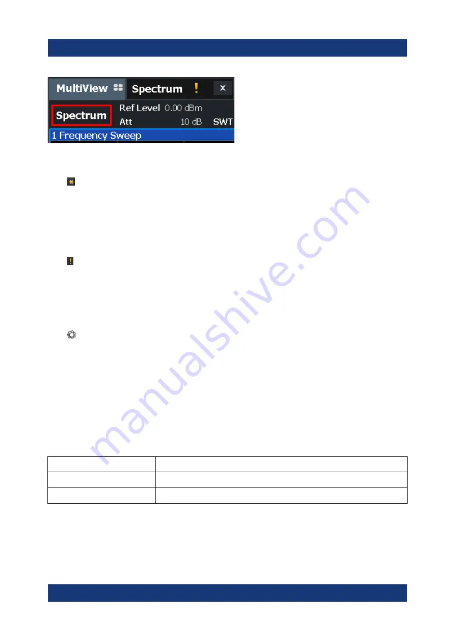
Icons in the channel bar
The yellow star icon on the tab label (sometimes referred to as a "dirty flag")
indicates that invalid or inconsistent data is displayed, that is: the trace no longer
matches the displayed instrument settings. Thiscan happen, for example, when
you change the measurement bandwidth, but the displayed trace is still based on
the old bandwidth. As soon as a new measurement is performed or the display is
updated, the icon disappears.
The icon indicates that an error or warning is available for that measurement
channel. This is particularly useful if the MultiView tab is displayed.
An orange "IQ" (in MSRA mode only) indicates that the results displayed in the
MSRA slave application(s) no longer match the data captured by the MSRA Mas-
ter. The "IQ" disappears after the results in the slave application(s) are refreshed.
The icon indicates the currently active channel during an automatic measure-
ment sequence (
Sequencer
functionality).
Channel-specific settings
Beneath the channel name, information on channel-specific settings for the mea-
surement is displayed in the
channel bar
. Channel information varies depending
on the active application.
In the Spectrum application, the R&S
FSW shows the following settings:
Table 7-1: Channel settings displayed in the channel bar in the Spectrum application
Ref Level
Reference level
m.+el.Att
Mechanical and electronic RF attenuation that has been set.
Ref Offset
Reference level offset
Understanding the Display Information


