Preparing for Use
R&S
®
SMU200A
18
Quick Start Guide 1007.9822.62 ─ 13
●
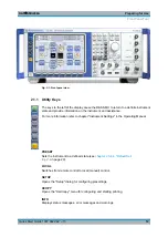
chapter "Baseband Input Settings Menu" in the Operating Manual.
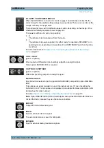
DATA
Signal for Path A only.
Input for external serial data signal in case of digital modulation.
Output for serial data signal in case of digital modulation.
For more information see:
●
chapter "Data and Signal Sources in Baseband" in the Operating Manual
●
chapter "Baseband Input Settings Menu" in the Operating Manual.
CLOCK
Signal for Path A only.
Input for external clock signal (bit or symbol clock, multiple of symbol clock) for synchro-
nizing the external data signal in case of multivalent modulation. The active edge can be
set.
Output for clock signal (bit or symbol clock) in the internal mode.
RF A, RF B
Outputs for RF signal of path A and path B.
NOTICE!
Maximum Input Levels. Do not overload the RF output. The maximum permis-
sible back-feed is specified in the data sheet.
TRIGGER 1
Input for triggering digital modulations, standards and ARB.
For more information see chapter "Global Trigger Clock Input Settings" in the Operating
Manual.
MARKER 1, 2
Outputs 1 and 2 for triggering and control of external devices with user-definable marker
signals.
The instrument provides four outputs for marker signals. Marker signals 1 to 3 are per-
manently assigned to the outputs; marker signal 4 can be routed to one of the four
USER outputs. The assigment is as follow:
Path A
●
Marker 1,2: BNC connectors MARKER 1 / 2 on the front panel.
●
Marker 3: MARKER 3 pin of AUX I/O connector on the rear panel.
●
Marker 4: BNC connector USER 1 or USER 2/3/4 pins of AUX I/O connector on rear
panel.
Path B
●
Marker 1: MARKER 1B output on rear panel.
●
Marker 2/3: MARKER 2 B / 3 B pins of AUX I/O connector on rear panel.
●
Marker 4: BNC connector USER 1 or USER 2/3/4 pins of AUX I/O connector on rear
panel.
For more information see section "Global Trigger/Clock/Input Settings" in the Operating
Manual.
Front Panel Tour
Summary of Contents for 1141.2005.02
Page 27: ......
Page 74: ...Preparing for Use R S SMU200A 57 Quick Start Guide 1007 9822 62 13 LXI Configuration ...
Page 75: ......
Page 95: ......
Page 135: ......
Page 141: ......
Page 144: ...Index R S SMU200A 127 Quick Start Guide 1007 9822 62 13 Winbar 89 Windows XP 33 access 34 ...


