


3-52
Programming and Parameters
PowerFlex 700S Phase II AC Drive User Manual -
Publication 20D-UM006G-EN-P – July 2008
337
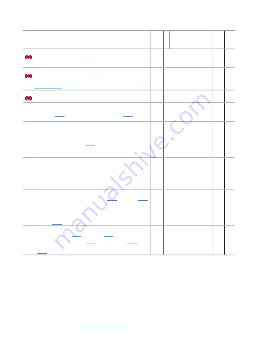
Mtr I2T Curr Min
Sets the minimum current threshold for the motor overload (I
2
T) function. The value indicates
minimum current at the minimum speed,
[Mtr I2T Spd Min], and these are the first
current/speed breakpoint. From this point the current threshold is linear to the value specified
by
[Motor OL Factor].
Units:
Default:
Min Max:
P.U.
0.5000
0.0500/2.0000
RW Real
338
Mtr I2T Spd Min
Sets the minimum speed for the motor overload (I
2
T) function. The value indicates minimum
speed below the minimum current threshold
[Mtr I2T Curr Min], and these are the first
current/speed breakpoint. From this point the current threshold is linear to the value specified
by the motor service factor
[Motor OL Factor]. For more information, please see
Units:
Default:
Min/Max:
P.U.
1.0000
0.0500/1.0000
RW Real
339 Mtr
I2T
Calibrat
Sets the current calibration level for the motor overload (I
2
T) function. The value indicates the
current level that the drive will fault at this current in 60 seconds.
Units:
Default:
Min/Max:
P.U.
2.0000
1.1000/4.0000
RW Real
340
Mtr I2T Trp ThrH
Displays the trip threshold current for the motor overload (I
2
T) function. The value depends on
the motor speed, and is calculated from the minimum current
[Mtr I2T Curr Min], the
minimum speed
[Mtr I2T Spd Min] and the motor service factor
[Motor OL
Factor].
Units:
Default:
Min/Max:
P.U.
1.1500
0.0500/2.0000
RO Real
341
Mtr I2T Count
The accumulator for Motor Overload detection (Motor I
2
T function). When the motor runs at
the over rated motor current, the accumulator starts counting up. If the motor runs at below
rated motor current, the accumulator counts down. If the value of this parameter exceeds 0.5,
the “Motor OLoad Pend” alarm (fault 12) occurs. If the value of this parameter exceeds 1.0,
the “Motor OLoad Trip” fault (fault 11) occurs. The value of this parameter is saved in
non-volatile memory after power-down if
[Control Options], bit 20 “Motor OL Ret” is
on. Toggling bit 20 of Par 153 [Control Options] clears the value of this parameter.
Note: This parameter was added for firmware version 3.01.
Default:
Min/Max:
0.0
0.0/1.5
RO Real
343
OL OpnLp CurrLim
Displays the current limit set by the Open Loop Inverter Overload (OL) function. This function
sets this current limit based on stator current feedback and the current ratings of the drive -
continuous and short term (three-second rating). Typically the drive will have a sixty-second
rating of 110% of continuous current and a three-second rating at 150% of the continuous.
Under normal operating conditions, the open loop function sets this current limit to the short
term (three-second) rating. If the function detects an overload, it lowers the limit to the
continuous level. After a period of time (typically one to three minutes), the function returns
the limit to the short term rating.
Units:
Default:
Min/Max:
P.U.
8.0000
0.0000/8.0000
RO Real
344 OL
ClsLp
CurrLim
Displays the current limit set by the Closed Loop Inverter Overload (OL) function. This
function will set a current limit level based on the values in
[Heatsink Temp] and the thermal characteristics of the drive. Under normal operating
conditions, the function typically sets the limit at 250% of the continuous drive rating. If the
function determines that the power device junction temperature is approaching maximum, it
will reduce this limit to the level required to prevent additional heating of the inverter. This level
could be as low as the continuous rating of the drive. If the inverter temperature decreases,
the function will raise the limit to a higher level. Disable this protection by setting bit 13 “OL
ClsLpDsbl” of
[Control Options].
Units:
Default:
Min/Max:
P.U.
8.0000
0.0000/8.0000
RO Real
345 Drive
OL
JnctTmp
Displays the calculated junction temperature of the power semiconductors in the inverter. The
calculation uses the values of
[Heatsink Temp],
[Iq Ref Limited], and inverter
thermal characteristics contained in the power EE memory. If this value exceeds the
maximum junction temperature (visible in
[Drive OL TP Data] when
[Drive OL
TP Sel] option 12 “fJunTmprMax” is selected), two faults occur: Inverter Overtemperature
Fault (fault code 15), and Junction Overtemperature Fault - indicated by bit 7 “Jnc OverTemp”
of
[Drive OL Status].
Units:
Default:
Min/Max:
degC
0.0000
-50.0000/300.0000
RO Real
No.
Name
Description
Values
Linkab
le
R
ead-Wr
ite
Da
ta
T
ype