Rockwell Automation Publication 440R-UM014D-EN-P - December 2019
19
Power, Ground, and Wire
Chapter 3
Monitoring Input
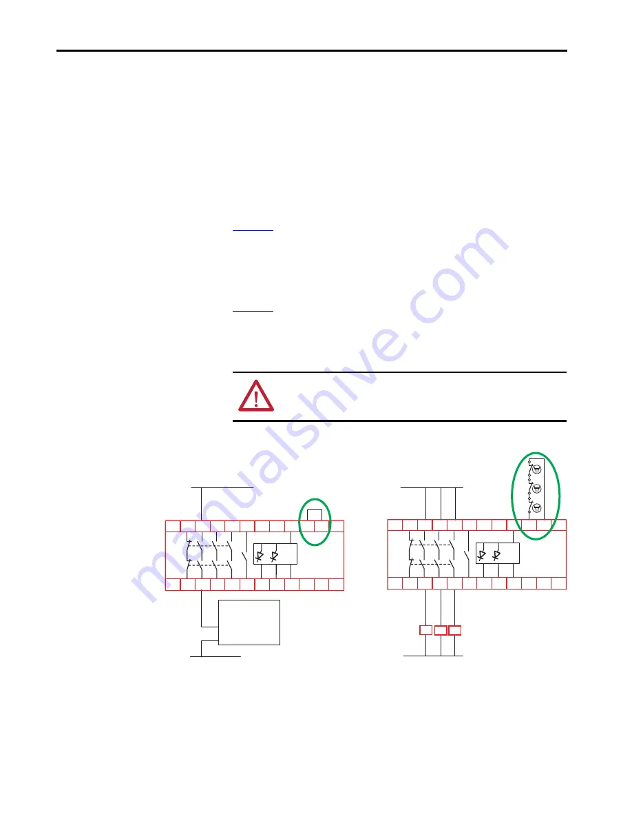
Monitoring of external devices, like safety control relays and safety contactors,
can be accomplished by adding their normally closed contacts between X1 and
X2. The safety outputs of the MSR55P safety relay are enabled only if the
feedback loop X1/X2 is closed while standstill is detected, that is the external
contactors/components are in initial state (N.C. contacts are closed).
The feedback circuit X1/X2 must be closed as long as the safety outputs are
disabled. If not, the ERR indicator shows fault code 4.
In some applications, where monitoring cannot be done, install a jumper
between X1 and X2. The jumper is shown in the No Monitoring diagram in
If additional devices must be controlled, safety control relays or contactors can
be connected to the safety outputs of the MSR55P safety relay. The MSR55P
safety relay can monitor the status of these devices by connecting their voltage-
free contacts in series, as shown in the Contactor Monitoring diagram in
The MSR55P safety relay is shipped from the factory with a jumper from
X1 to X2.
Figure 12 - Examples of Feedback Monitoring Circuits
ATTENTION:
Terminals X1-X2-X3 have electrical connections to measuring
inputs L1-L2-L3. Voltage-free contacts that are rated for L1-L2-L3 voltage
must be used for these connections.
K3
K2
K1
K2
K3
Guard Locking Device
(Power to Unlock)
Unlock Command
24V Com
A2
X1 X2
L3
L2
L1
X3
34 44
A1
A3
33
23
11
24
12
ON ERR A4
54
43 53
A2
X1 X2
L3
L2
L1
X3
34 44
A1
A3
33
23
11
24
12
ON ERR A4
54
43 53
K1
24V Com
24V DC
No Monitoring
Contactor Monitoring


