background image

34

Rockwell Automation Publication IOLINK-UM001A-EN-P - August 2017

Appendix A

Install the Add-on Profile

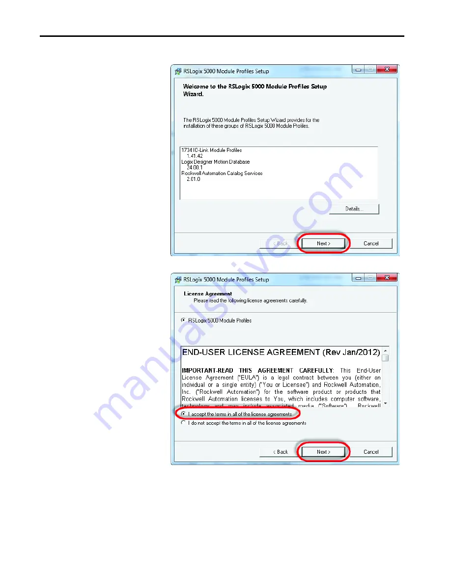
3. Click Next to install the IO-Link module profiles.

4. Accept the license agreements and click Next.

5. Follow the module-profiles installation wizard.

Summary of Contents for Allen-Bradley 836P Series

Page 1: ...IO Link for Solid state Pressure Switches Catalog Number 836P Dx User Manual OriginalInstructions...

Page 2: ...nformation circuits equipment or software described in this manual Reproduction of the contents of this manual in whole or in part without written permission of Rockwell Automation Inc is prohibited T...

Page 3: ...How Does IO Link Work 8 Transmission Rates 9 Transmission Quality 9 Response Time of the IO Link System 9 IO Link Data Types 9 Process Data 10 Value Status 10 Device Data 10 Events 10 Accessing IO Li...

Page 4: ...ter Connection Procedure 31 AppendixA Install the Add on Profile Introduction 33 Perform the Installation 33 AppendixB Message Structure and Configuration Examples Configure a Message Instruction 37 E...

Page 5: ...mless connection and commission of control components These features allow you to reap the benefits of an IO Link solution with access to more detailed and customized plant floor information than othe...

Page 6: ...en Bradley distributor or Rockwell Automation sales representative Resource Description Solid state Pressure Switches User Manual publication 836P UM001 Describes the procedures thatare usedto install...

Page 7: ...in which the master controls the interface access to the sensor The option of using the intelligence that is integrated into the sensor provides you with new methods to commission your device Benefits...

Page 8: ...s instead of hours modify sensor parameters to produce different finished goods Descriptive Tags Faster programming during initial setup More efficient troubleshooting process data tags are named base...

Page 9: ...vice contains a value for the minimum cycle time of the device This value indicates the time intervals at which the master addresses the device The value has a large influence on the response time In...

Page 10: ...ad from the device Read Events When an event occurs the device signals the presence of the event to the master The master then reads out the event Events can be error messages and warnings maintenance...

Page 11: ...tem are transmitted to the device Then the cyclic exchange of the process data and value status begins Assign Device Parameters A device that is built for a specific application requires changes to pa...

Page 12: ...the integration of the Rockwell Automation IO Link devices to the Rockwell Automation architecture there is an IO Link AOP available for the 1734 4IOL master module The use of an AOP simplifies the s...

Page 13: ...g damaged sensors is easy Simply remove the old Allen Bradley sensor and connect the new one the controller automatically sends the configuration to the new sensor Application Specific Name ASN When a...

Page 14: ...14 Rockwell Automation Publication IOLINK UM001A EN P August 2017 Chapter 1 836P Pressure Sensor with IO Link Overview Notes...

Page 15: ...ware Required 836P solid state pressure display sensor CompactLogix or ControlLogix PLC platform POINT I O communications interface 1734 AENTR POINT I O IO Link master module 1734 4IOL POINT I O termi...

Page 16: ...ctLogix controller via EtherNet IP When adding an 836P pressure switch to the 1734 4IOL master module complete the following steps 1 Provide power to the 1734 AENTR adapter 2 Set the node address on 1...

Page 17: ...4 AENTR adapter and 1734 4IOL IO Link master module to Controller Organizer Tree see Configure the IO Link Master on page 23 and Register the 836P IODD on page 27 for detailed instructions IMPORTANT O...

Page 18: ...18 Rockwell Automation Publication IOLINK UM001A EN P August 2017 Chapter 2 Set up the 836P Sensor for IO Link Mode Notes...

Page 19: ...owing procedure 1 Double click the Studio 5000 icon 2 Click New Project 3 To program the controller select the controller that is used In this example it is the 1769 L24ER CompactLogix IMPORTANT If th...

Page 20: ...Project 4 After selecting the controller name the project and click Next In this example the project name is Project836P 5 Once the project opens up configure the IP address of the controller to help...

Page 21: ...nline to start communicating The next step is to configure the IO Link Master page 23 AOP Installation Next verify that Studio 5000 contains the 1734 4IOL IO Link AOP Version 20 or higher of Studio 50...

Page 22: ...22 Rockwell Automation Publication IOLINK UM001A EN P August 2017 Chapter 3 Create a Project Notes...

Page 23: ...2017 23 Chapter 4 Configure the IO Link Master Configuration Procedure 1 Verify that the controller is offline to configure the IO Link Master 2 In the controller organizer tree find Ethernet under I...

Page 24: ...odule window appears and shows the available modules Select 1734 AENTR 1734 Ethernet adapter 2 port twisted pair media and click Create 4 Name the Ethernet adapter in this example our adapter name is...

Page 25: ...omation Publication IOLINK UM001A EN P August 2017 25 Configure the IO Link Master Chapter 4 5 The 1734 AENTR now appears in the Controller Organizer tree 6 Right click on 1734 AENTR adapter and selec...

Page 26: ...4IOL and click Create 8 Another screen appears showing the IO Link Configuration screen 9 Name the IO Link Master and click OK You can now configure your 836P pressure switch To configure the sensor a...

Page 27: ...r integrated into the system environment By default the IODDs are already located in the AOP Library If the IODD file for the 836P cannot be located in the library it can be downloaded from http compa...

Page 28: ...blication IOLINK UM001A EN P August 2017 Chapter 5 Register the 836P IODD The IO Link configuration screen appears 3 Right click the left section of the screen where the channel information is located...

Page 29: ...2017 29 Register the 836P IODD Chapter 5 4 Click the Register IODD button A new window appears Click the Register IODD button of the new window The new window enables you to locate the IODD file in yo...

Page 30: ...30 Rockwell Automation Publication IOLINK UM001A EN P August 2017 Chapter 5 Register the 836P IODD Notes...

Page 31: ...k Master Connection Procedure Once the IODD file is registered the sensor must be connected to the IO Link master The controller must always be off line to add a device to the IO Link master 1 Right c...

Page 32: ...ect the 836P Sensor to the IO Link Master 3 Select the appropriate sensor and double click or click Create 4 Click OK to accept the configuration 5 Click Go Online to communicate Publication 836P UM00...

Page 33: ...l Automation network The AOP simplifies the setup of devices because it presents the necessary fields in an organized fashion The AOP allows for install and configuration of systems in a quick and eff...

Page 34: ...lication IOLINK UM001A EN P August 2017 Appendix A Install the Add on Profile 3 Click Next to install the IO Link module profiles 4 Accept the license agreements and click Next 5 Follow the module pro...

Page 35: ...ell Automation Publication IOLINK UM001A EN P August 2017 35 Install the Add on Profile Appendix A 6 Verify that the Install option is selected and click Next 7 Review the install details and click In...

Page 36: ...A Install the Add on Profile 8 The installation process begins This process can take several minutes Once completed the Next button is available 9 Click Next 10 Click Finish and review the release not...

Page 37: ...d Message In this example the steps that are shown are necessary to read the IO Link parameter value for Vendor Name from the 836P sensor The screen capture that is shown is the Message Configuration...

Page 38: ...CIP Generic 2 Service Type The service type is Custom Custom 3 Service Code Established from Service Code Table 4D 4 Class The class is 3a3 3a3 5 Instance Established from Appendix A Identifies the I...

Page 39: ...as ASCII the name Allen Bradley is displayed Example Format of a Write Message It is possible to Write a unique name to the 836P sensor This Parameter is called Application Specific Name In the Device...

Page 40: ...nfiguration dialog box to Write Test to the Application Specific Name in the 836P pressure switch Item Description Value 1 Message Type The message type is CIP Generic CIP Generic 2 Service Type The s...

Page 41: ...ated either by reading the value of Index 24 in the sensor or viewing the 1734 4IOL configuration To view the configuration of the 1734 4IOL follow these steps 1 Click the 1734 4IOL in the I O Configu...

Page 42: ...ge Data Format Source Length 1 byte Table 6 Write Index 4E Message Data Format Source Length 1 byte Number of bytes of data being written Service Code Hex Need in Implementation Service Name Descripti...

Page 43: ...ic 10 device 10 process 10 data type IO Link 9 descriptive tag 8 device data 10 profile 8 device parameter assign 11 diagnostics real time 8 E event 10 example configuration 37 F feature IO Link 13 H...

Page 44: ...esponse time 9 S seamless integration 7 sensor health status 8 service code 42 set up hardware 16 IO Link mode 15 software 15 source length 42 start up I O system 11 status value 10 structure message...

Page 45: ......

Page 46: ...directly to a technical support engineer http www rockwellautomation com global support direct dial page Literature Library Installation Instructions Manuals Brochures and Technical Data http www rock...

Reviews: