


90
Rockwell Automation Publication 35-UM001A-EN-P - May 2022
Chapter 6 Safety Functions
The safety supervisor state provides information on the state of the integrated
safety connection and the mode of operation. There is only one safety
supervisor object per drive module.
shows the message instruction parameter needed to query the Safety
shows the possible response values and their
relation to the safety connection. For a message instruction example, see
Table 21 - Safety Supervisor State: MSG
Table 22 - Safety Supervisor States
STO Bypass Operation
To support commissioning of the product, a STO bypass plug may be used to
enable torque. The STO bypass plug can be used on either pair of inputs to
enable torque.
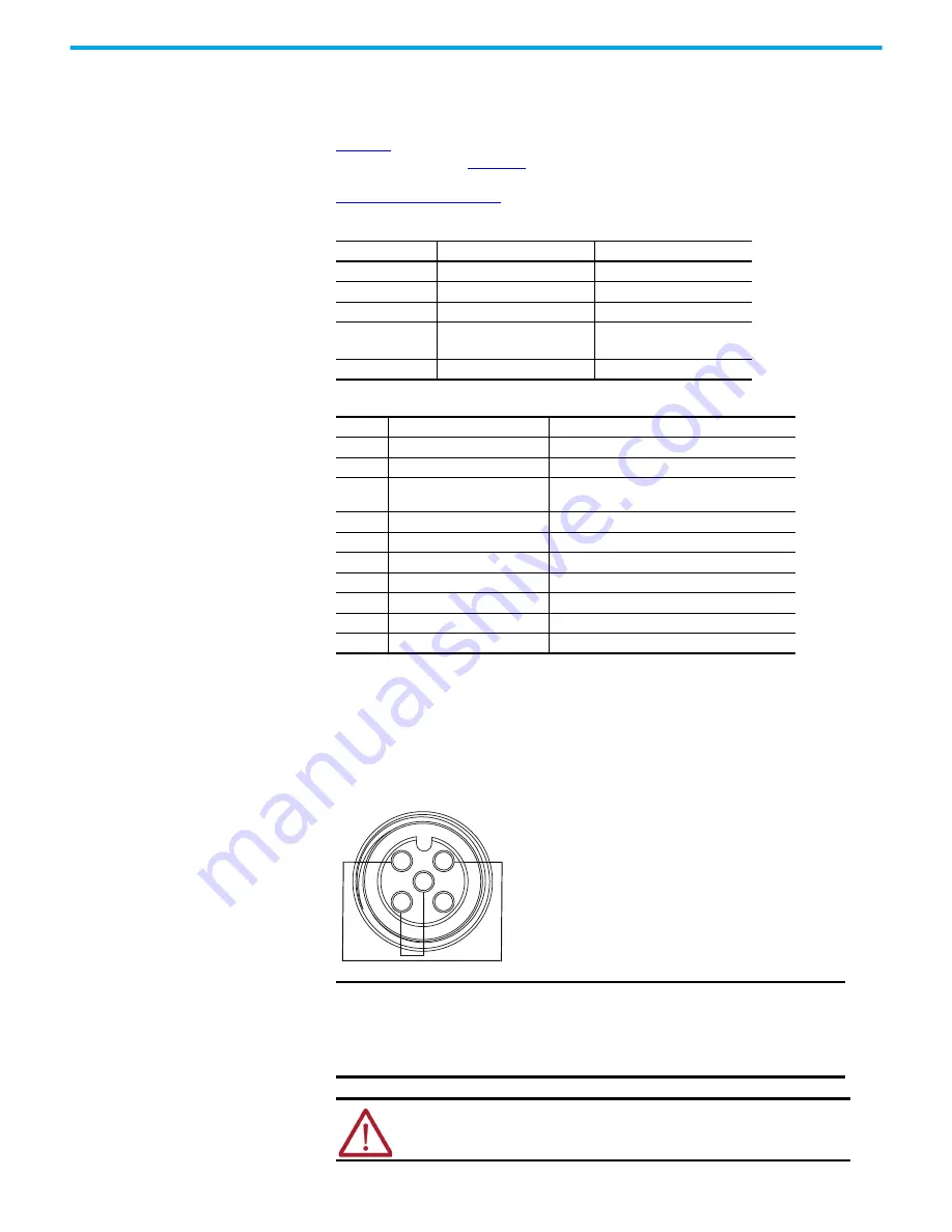
Figure 33 - Hardwired STO - Safety Bypass Plug
Parameter
Value
Description
Service Code
0x0E
Get attribute single
Class
0x39
Safety supervisor
Instance
1
Revision
Attribute
0x0B
11
(decimal)
Device status
Data Type
SINT
Short integer
Value
Display Text
Definition
1
Testing
Device is performing test diagnostics
2
Idle
No active connections
3
Test Flt
A fault has occurred while executing test
diagnostics
4
Executing
Normal running state
5
Abort
A major recoverable fault has occurred
6
Critical Flt
A critical fault has occurred
7
Configuring
Transition state
8
Waiting
Out-of-box state
51
Wait w Trq
Out-of-box state
52
Exec w Trq
STO bypass state
IMPORTANT
To use the 35S drive in an application without safety or to bypass
the STO feature while commissioning or testing the drive, the
drive must be in Hardwired mode and either safety input pair
must be wired to enable torque. The safety bypass jumper plug
can be used for this purpose.
ATTENTION:
If you bypass the STO feature, the safety system permits
motor torque that could result in unintended motion. Use additional
preventive measures to maintain the safety integrity of the machinery.
2
3
5
4
1
Pin 1: Test Output 1
Pin 2: Safety Input 1
Pin 3: Input Common
Pin 4: Safety Input 0
Pin 5: Test Output 0


