14
Rockwell Automation Publication 1715-UM001J-EN-P - December 2020
Chapter 1 Redundancy System Overview
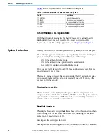
lists the 1715 modules that can be used in this system.
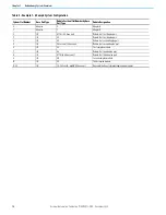
.
1715 I/O Modules in SIL 2 Applications
With the inclusion of diagnostics for the CIP messaging channel, the 1715
Redundant I/O system can be used for SIL 2 safety applications. For
information about SIL 2 safety applications, see
and
System Architecture
The 1715 Redundant I/O System operates with a pair of 1715-AENTR adapters.
When designing your control system by using the 1715 Redundant I/O System,
you can use digital and analog I/O modules in one of these ways:
•
One I/O module in Simplex mode
•
One I/O module with the option to add a second module
•
A pair of I/O modules that work in Duplex mode
You must decide the layout of your I/O before building your system, but you
can add more I/O at any time.
The use of termination assemblies communicates the I/O mode of operation
you choose (Simplex or Duplex) to your system through the backplane (the
adapter and I/O base units).
Termination Assemblies
The termination assembly (TA) matches your software configuration for
simplex or duplex. Attached to an I/O base, the TA can start in any slot and can
span multiple connected bases. When modules are used in Duplex mode, one
module can be absent and the system still runs.
Base Unit Structure
The adapter base unit is always the leftmost base unit in the connection chain.
The total length of the base unit connection chain, including all expansion
cables cannot exceed 10 m (32.81 ft).
An adapter always occupies slot 0 or 1.
An adapter base unit can support up to 8 I/O base units (up to 24 I/O modules).
Table 1 - Modules Available for the 1715 Redundant I/O System
Cat. No.
Description
1715-AENTR x 2
A pair of Ethernet adapters
1715-IB16D
A 16-channel digital input module
1715-OB8DE
An 8-channel digital output module
1715-IF16
A 16-channel analog input module
1715-OF8I
An 8-channel analog output module


