Specifications
A-3
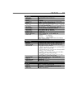
Control Features
PWM Algorithm
Sine Weighted PWM with Harmonic Compensation
Switching Device
IGBT
V/Hz Ratio
Programmable
Carrier Frequency
Adjustable from 2 to 8kHz in 100 Hz Increments (Factory Default is 4kHz)
DC Boost
Adjustable — Select from a Family of Boost Curves
Current Limiting
Software Controlled, Coordinated for Drive and Motor Protection — Programmable
from 1 to 180% of Drive Output Current
Motor Protection
I
2
t Overload Protection — 150% for 60 Seconds, 200% for 30 Seconds
Overload Pattern #0
Flat Response Over Speed Range (No Speed Compensation)
Overload Pattern #1
Speed Compensation Below 25% of Base Speed
Overload Pattern #2
Speed Compensation Below 100% of Base Speed
Accel/Decel Time(s)
0.1 to 600 Seconds
S-Curve Accel/Decel Time(s)
0 to 100% of Accel/Decel Time — Not to Exceed 60 Seconds
Stopping Modes
4 Programmable Modes:
Ramp to Stop —
0.1 to 600 Seconds
Coast to Stop —
Stops All PWM Output
DC Injection Braking — Applies DC Voltage to the Motor for 0 to 25 Seconds
DC Injection Braking with Auto Stop
Protective Features
Overcurrent
Programmable limit, 200% of Hardware Limit, 300% of Instantaneous Fault
Excessive Temperature
Embedded Temperature Sensor Trips if Heatsink Temperature Exceeds 95
°
C
Over/Under Voltage
DC bus voltage is monitored for safe operation.
• For 200-240VAC input drives, the overvoltage trip occurs at a bus voltage of 400VDC
(equivalent to a 290VAC incoming line voltage).
• For 380-460VAC input drives, the overvoltage trip occurs at a bus voltage of 800VDC
(equivalent to a 575VAC incoming line voltage).
• For 200-240VAC input drives, the undervoltage trip occurs at a bus voltage of
210VDC (equivalent to a 150VAC incoming line voltage).
• For 380-460VAC input drives, the undervoltage trip occurs at a bus voltage of
390VDC (equivalent to a 275VAC incoming line voltage).
Control Ride Through
Minimum Ride Through is 0.5 Seconds — Typical Value is 2 Seconds
Ground Short
Any Output Phase to Ground Short
Faultless Ride Through
100 Milliseconds
Output Short Circuit
Any Output Phase to Phase Short
Programming
Programmer
Optional — Removable Program Keypad Module
Display Type
6 Character LED — Two Digit Parameter Number and Four Digit Value
Keypad Controls
Speed, Run, Stop and Direction
Summary of Contents for Allen-Bradley 160 SSC Series
Page 12: ...1 6 Getting Started End of Chapter ...
Page 58: ...5 20 Parameters and Programming End of Chapter ...
Page 66: ...A 4 Specifications End of Chapter ...
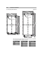
Page 75: ...Accessories and Dimensions B 9 Drilling Template A Figure B 10 ...
Page 76: ...B 10 Accessories and Dimensions Drilling Template B Figure B 11 ...
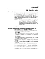
Page 82: ...C 6 CE Conformity End of Chapter ...
Page 87: ......


