


Operation
Theory of Operation
234
MagneMotion
Rockwell Automation Publication MMI-UM007F-EN-P - September 2020
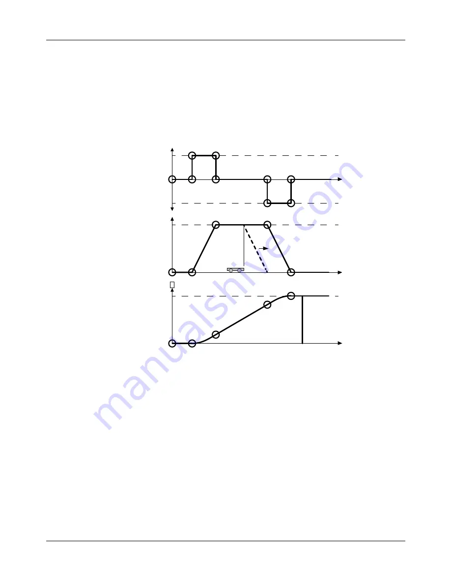
Safe Stopping Distance
Standard vehicle control makes sure that vehicles always have a safe stopping distance
(brick-wall headway).
shows acceleration, velocity, and position versus time for
the standard vehicle motion profile. Permission for vehicle motion is granted as required for
the vehicle to maintain its motion profile (solid heavy line) and provide brick-wall headway
(dashed heavy line) based on the current velocity and commanded acceleration of the vehicle.
The brick-wall headway distance can be found by dividing the square of the current velocity
of a vehicle by twice its acceleration (V
2
/2a).
Figure 6-5: Vehicle Motion Profile
Thrust Limitations
When a vehicle is commanded with a higher acceleration rate than the motor can provide, the
vehicle falls behind its ideal move profile while accelerating.
shows both the ideal
move profile (solid line) and the degraded move profile (dashed line).
In addition, and more critically, the vehicle is not able to decelerate at the specified rate and
overshoots its destination as shown by the dashed line in
. This behavior can result
in vehicles colliding with other vehicles or switch components, or loss of control of a vehicle
as it exits the area where it has permission to move. Thus, it is important to avoid command-
ing a move with an acceleration that is higher than the deceleration capability of the system.
The precise deceleration capability depends on vehicle mass (including payload), center of
gravity location, speed, and track geometry. Furthermore, the thrust capability of the motors is
reduced in proximity to the gaps between motors.
Destination
Vlimit
-Alimit
+Alimit
Time
Time
Time
Po
sit
io
n
Ve
lo
ci
ty
Acce
le
ra
tio
n