


Installation
Transport System Installation
198
MagneMotion
Rockwell Automation Publication MMI-UM007F-EN-P - September 2020
Motor Sense and Drive Cables
When using a 1 m QSHT motor, there is one Sense cable and one Drive cable that is con-
nected from each inverter to each motor. When using two consecutive 1/2 m QSHT motors,
there are two Sense cables and two Drive cables, one set per motor.
1.
For 1 m motors, connect a drive cable from Stator Inverter Output A and Stator
Inverter Output B on the inverter to the Drive connector on the motor (see
). Tighten the connector on the motor with soft jaw pliers (the connector
snaps into place when it reaches the locked position). Route the cable so it is shielded
from damage and can be easily accessed for service.
For 1/2 m motors, connect a drive cable from Stator Inverter Output A on the inverter
to the Drive connector on the first 1/2 m motor (see
). Connect a drive
cable from Stator Inverter Output B on the inverter to the Drive connector on the sec-
ond (consecutive) 1/2 m motor (see
). Tighten the connector with soft jaw
pliers (the connector snaps into place when it reaches the locked position). Route the
cable so it is shielded from damage and can be easily accessed for service.
The factory-supplied MMI-HT-Series motor cables are shielded and the braided cable
shield must terminate at the inverter during installation as shown in
exposed area must be clamped (with the clamp provided) at the bottom front of the
inverter. Clamp spacers, included with the inverters and held captive by rivets, are
needed for all cable installations, and must not be removed.
A.
Loosen the clamp knob.
The drive cable shield attaches to the inverter cable clamp. Clamp spacers are
included to make sure of a tight fit within the drive clamp.
B.
Position the exposed portion of each cable braid directly in line with the clamp.
C.
Hand tighten the clamp knob.
Make sure that the cable clamp tightens around the cable shield and provides a
good bond between the cable shield and the drive chassis. Only finger-tight
torque on the clamp knob is required. The cable should not move within the
clamp under its own weight or when slight pressure is applied by hand.
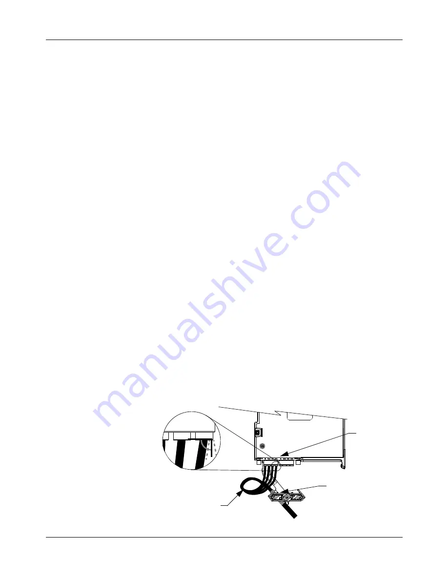
Figure 5-11: QSHT 5700 Inverter Cable Clamp
Service loops provide stress relief
and the conductors enter into the
motor connectors at approximate-
ly 90° (between 75° and 105° is
acceptable).
75° to 105° Entry
into connectors
Clamp compressed
around shield close
to heat shrink tubing
Motor Drive
Connector