background image

I) Attaching  to the Power Unit

Note:


When you ordered your BrushHound product, details about your Power Unit were provided to custom match your 

Attachment to your Power Unit.  While BrushHound products can be attached to a variety of different backhoes and exca-
vators, your Attachment is specifically configured for your Power Unit and can not necessarily be placed on another Power 
Unit as is.  Specifically, the mount and hydraulic motor were selected to mate to your Power Unit’s arm and optimize per-
formance based on your hydraulic system, respectively.  Your Attachment should only be connected to Power Units that 
share the same specifications as the information on the Power Unit you provided.  To connect your Attachment to another 
Power Unit, contact your nearest BrushHound Dealer.   

The person that is attaching your BrushHound product should be familiar with the attachment and removal of reg-

ular buckets from a backhoe or excavator and be able to do so safely.  Attachment should be performed on flat ground 
away from obstructions.  During attachment, keep hands out of pinch points and away from the blades to avoid injury: 

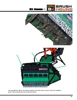
1) Ensure that the appropriate mount for the Power Unit is attached to the BrushHound product  using the 4 provided 1”

bolts (See the “Optional Mounts” section for details on switching mounts).

2) Lower the Power Unit’s arm into position and attach the mount in the same way you would attach the bucket.

3) Connect Attachment’s hydraulic lines to your Power Unit’s auxiliary hydraulic circuit.  If your Power Unit does not have

an auxiliary circuit, fully retract the thumb and use your thumb’s hydraulic circuit (See the “Hydraulic Plumbing” sec-
tion for details on the appropriate connection of hoses to the Power Unit).  Ensure that all fittings are connected tight-
ly and that quick couplers have fully engaged.

4)

Make sure that your Power Unit is set to “Hydraulic Breaker Mode” (one way flow).  If your Power Unit does not have

a hydraulic breaker mode or one way flow, you may need to install a case drain line.

II) Starting Procedure

The Operator should be properly trained on the use of your BrushHound Attachment and wearing the appropriate 

safety gear.  Do not start the Power Unit until the Attachment has been checked for proper assembly and installation.  This 
includes the appropriate connection of the mount and hydraulic connections as well as the proper functioning of all safety 
devices on both the Power Unit and the Attachment.  Clear the work area of all bystanders and children: 

1) Check that the attachment is in the down position and that the blades are not in contact with ground.  Start engine

and set throttle to idle.  Never engage the auxiliary hydraulic flow  with the motor above idle speed.

2) With the motor at low RPM engage the auxiliary hydraulic flow.

3) Slowly bring the throttle up to maximum flow. If the Attachment produces excessive noise or vibration, disengage the

auxiliary hydraulics and  shut down the Power Unit immediately.  Determine the cause of the problem and correct it
before continuing with its operation.

4) Attachment is ready for operation.

2) Basic Operation

www.rockhound.com 

Summary of Contents for BrushHound 30EX

Page 1: ...BRUSHHOUND EX OWNER S MANUAL EX Series by PO Box 220 2507 Tully Road Hughson CA 95326 USA 800 426 5615 www Valleytoolmfg com...

Page 2: ......

Page 3: ...lubricated Buyer is shown all grease fittings and proper daily maintenance routine Buyer is shown correct operation procedures including correct height of attachment All bolts checked for tightness A...

Page 4: ......

Page 5: ...dure 6 Running Your Attachment 7 Basic Guidelines for Running Your Attachment 9 Transport Removal Storage 9 Adjustments Maintenance Service Safety 11 Lubrication 11 Wearable Component Maintenance 11 K...

Page 6: ...s previously manufactured If at any time you require additional information consult your authorized dealer or the customer service depart ment ATTENTION The safety of the operator was one of the prima...

Page 7: ...ent of attachment knives explained to end user ALL safety precautions thoroughly read and understood Warranty RockHound Attachments guarantees the BrushHound Brush Shredder to be free from defect in m...

Page 8: ...e minimum safe distance from discharge is 300 ft Under no circumstances should the blades of this machine come into contact with the ground or should the machine be curled in such a way that the blade...

Page 9: ...racked or broken blades with new ones Do not attempt to weld damaged blades This can cause damage that could result in the blade being thrown from the shredder Wear gloves and eye protection and exerc...

Page 10: ...to your Power Unit s auxiliary hydraulic circuit If your Power Unit does not have an auxiliary circuit fully retract the thumb and use your thumb s hydraulic circuit See the Hydraulic Plumbing sec tio...

Page 11: ...essurized even when turned off before approaching or allowing others to approach the Attachment 6 Visually inspect hydraulic motor motor protection valve and other areas for signs of excessive heat de...

Page 12: ...Down Shredding Thicker brush and trees can be shredded from the top down Starting from a stationary position raise the boom and curl the head so that it is mostly perpendicular with the tree but not...

Page 13: ...8 House Rotation Shredding EX Series by Top Down Shredding...

Page 14: ...cutting large diameter material lay the tree down and plane the tree from side to side This will proved a better finer mulch and is quicker and easier than trying to grind a tree of 6 diameter from t...

Page 15: ...e it from the Attachment d Storage on Power Unit When leaving the Attachment unattended while still attached to the Power Unit 1 Find a suitable flat location to leave the Power Unit and Attachment 2...

Page 16: ...ign of chronic over greasing a Idle Bearing The idle bearing is located under the Idle Side Bearing Cover and has a grease fitting located on the bearing s mounting flange The idle bearing comes pre p...

Page 17: ...bearings should be replaced every 1500 2000 hours of operation depending on the environment and us age conditions d Safety Guards Safety guards are in place for the protection of the Operator bystande...

Page 18: ...aning your Attachment regularly will help prolong the life of both the paint and the safety decals as well as minimize the risk of unintentional fire 1 Check for excessive grease in the bearing areas...

Page 19: ...EX Series by 16 Cleaning Locations Debris can collect on bearings in the motor area on top or on the rear deflection guard Use a power washer to keep these areas clean...

Page 20: ...llows a Pressure In shown as male quick connect This attaches to your Power Unit s high pressure line On some units it may be necessary to switch the male and female quick connectors depending on the...

Page 21: ...ick couplers may need to be ex changed on hose ends depending on the power unit If oil is flowing and there is no movement this may be due to coupler orientation 16 EX Series by Pressure In Male Quick...

Page 22: ...e drum ever be reversed Q Sometimes the attachment loses RPM very rapidly even though its use has not changed why A Allow drum RPM to fully recover before continuing with operation The drum acts as a...

Page 23: ...18 EX Series by Serial Number Plate...

Page 24: ...EX Series Brush Shredder Parts Catalog 19 www rockhound com...

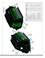
Page 25: ...aring Guard 1 4 Motor Guard Top 1 BC 40EX 5 Motor Guard Bottom 1 BC 40EX 1 6 Reinforced Thumb 1 7 Document Holder 1 DC 50 8 Chains CH 1000 9 Chain Retention Rods 40 2 CR 40 Chain Retention Rods 30 2 C...

Page 26: ...ention Ring 1 8 Dampener Washer 1 CD 40EX 13A 9 Wire Guard Drive Side CD 40EX 16A 10 Wire Guard Idle Side 1 CD 40EX 17 11 Cutter Drum Assembly 40 EX 1 CD 40EX Cutter Drum Assembly 40 HD 1 CD 40EX HD C...

Page 27: ...420 4 Hose Barb 90 2 HY 2425 5 3 4 Hydraulic Hose 100 2 HY 2550 6 3 4 Female Flatface Coupler 1 HY 2530 7 3 4 Male Flatface Coupler 1 HY 2530 8 1 x 3 4 90 Adapter 2 HY 2545 9 Check Valve 1 10 Plug 11...

Page 28: ...BRUSHHOUND DEFENDER OWNER S MANUAL EX Series by PO Box 220 2507 Tully Road Hughson CA 95326 USA 800 426 5615 www Valleytoolmfg com...

Reviews: