background image

Roche Diagnostics


C-12

Operator’s Manual · Version 3.1

8 General maintenance

Cedex Bio System

Maintenance actions

Clean the probe manually

f

Utilities

 > 

Maintenance

 > 

Clean Probe Manually

You must clean the probe regularly by hand to prevent any build up of deposits that 
may affect results.

Operator time

Approximately 1 minute.

Prerequisites

The system must be in 

Standby

 status.

Tools and materials required

m

70% ethyl alcohol

m

Tissues

a

To clean the probe
1

Select the maintenance action 

Clean Probe Manually

.

2

Press .

The maintenance definition screen is displayed.

3

Press .

The system deactivates the transfer motors.

4

Remove the transfer head cover.

Press the release buttons on both sides and lift.

5

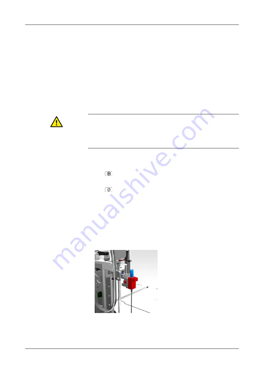
Remove the probe with its holder.

o

Remove the tube from at least the first two tubing clips.

o

Press the release button on the side of the probe holder carriage and lift the 
probe holder with the probe. Be careful not to pull the tubing.

Make sure that you have read and understood section 

Safety information

 on page C-8. 

The following warning messages in particular are relevant:

o

Injury through working solutions

 on page C-8.

o

Incorrect results due to build-up of contaminants

 on page C-8.

o

Infection by biohazardous materials

 on page C-8.

Summary of Contents for Cedex Bio

Page 1: ...Cedex Bio System Operator s Manual Software Version 2 1...

Page 2: ...d Software updates are done by service representatives Intended use The Cedex Bio instrument is a continuous random access analyzer intended for the determination of chemical and biochemical parameter...

Page 3: ...ng the shift B 10 Preparing the system B 12 Analyzing samples B 34 Validating sample results B 51 Performing calibrations B 59 Performing QC B 68 Finishing the shift B 77 Logging off B 88 Shutting dow...

Page 4: ...ription Overview E 5 Hardware E 9 Basic operation E 12 Technical specifications E 13 13 ISE operation Daily operation E 17 Replacing ISE fluid bottles E 30 Replacing electrodes E 32 Cleaning the ISE t...

Page 5: ...nts at the beginning of the manual and each chapter In addition a complete index can be found at the end Online Help system The Cedex Bio instrument has a context sensitive online Help feature to aid...

Page 6: ...the buttons is used without color or navigation indicators Screenshots The screen representations shown in this publication are for illustrative purposes only The screens do not necessarily show valid...

Page 7: ...i gratia for example EMC Electromagnetic compatibility EN European standard i e Id est that is to say IEC International Electrical Commission ISE Ion selective electrode LED Light emitting diode LIS L...

Page 8: ...centigrade L microliter m micrometer A amp re cm centimeter h hour Hz hertz LB pound weight in inch kg kilogram kVA kilo volt ampere L liter m meter MB megabytes min minute mL milliliter mm millimeter...

Page 9: ...1 Safety A 3 2 Introduction to the instrument A 15 3 Hardware A 37 4 Software A 67 System Description A...

Page 10: ......

Page 11: ...peration and maintenance A 6 Biohazardous materials A 6 Waste A 7 Reagents and other working solutions A 7 Installation A 7 Environmental conditions A 7 Power interruption A 8 Electromagnetic devices...

Page 12: ...Roche Diagnostics A 4 Operator s Manual Version 3 1 1 Safety Cedex Bio System Table of contents Legal liability A 12 Safety labels A 13...

Page 13: ...us situation which if not avoided may result in minor or moderate injury NOTICE Notice Indicates a hazardous situation which if not avoided may result in property damage WARNING Injury from heavy load...

Page 14: ...te them as instructed on the screen WARNING Personal injury or damage to the analyzer due to contact with instrument mechanism Do not touch any parts of the instrument other than those specified Durin...

Page 15: ...mmediately with water and apply a dis infectant Consult a physician WARNING Injury through reagents and other working solutions Direct contact with reagents cleaning solutions or other working solutio...

Page 16: ...found to comply with the limits for Class B digital device pursuant to part 15 of the FCC Rules These limits are designed to provide reason able protection against harmful interferences when the equip...

Page 17: ...ohazard material CAUTION Fatigue due to long hours of operation Looking at the monitor screen over an extended period of time may lead to fatigue of your eyes or body Take a rest for 10 to 15 minutes...

Page 18: ...low connection to authorized external devices only o Ensure that all external devices are protected by appropriate security software o Ensure that access to all external devices is protected by approp...

Page 19: ...se For details see document CedexBio Sys tem License Notes The portions of used open source software are part of MIKRAPs CPU X168LCD NET board support package and may be obtained from Mikrap AG info m...

Page 20: ...re contaminated or not If contaminated treat in the same way as the instrument Legal liability It is the users sole responsibility to determine whether they activate the TRL Check feature and if they...

Page 21: ...g out maintenance procedures When working with the instrument be sure to observe both the safety labels on the instrument and the safety notes in the Operator s Manual A This label on the electrode bl...

Page 22: ...Roche Diagnostics A 14 Operator s Manual Version 3 1 1 Safety Cedex Bio System Safety labels...

Page 23: ...ex Bio instrument Overview A 17 Principles of operation A 19 User interface A 20 Wizards A 21 Daily operation A 22 Overview A 22 Reagent and diluent handling A 24 Calibration A 26 Calibration type A 2...

Page 24: ...Roche Diagnostics A 16 Operator s Manual Version 3 1 2 Introduction to the instrument Cedex Bio System Table of contents...

Page 25: ...tenance improves up time and reduces maintenance costs o Adaptable user interface The built in color touchscreen process driven software and reagent and sample barcode entry adapts to users of differe...

Page 26: ...ap covers wash station ISE tower tubing B Main cover covers rotor reagents cuvettes photometer unit C Main switch D Transfer head holds probe E Rear service flap covers computer boards power supply de...

Page 27: ...and tubing are flushed with water and cleaner 3 Wait The fluid needs to reach the prescribed temperature Such a phase can last several cycles During the wait cycles activities for other tests are per...

Page 28: ...details on orders and Utilities for administration tasks e For details on the user interface see Chapter 4 Software The following is an example of a screen It contains the full range of display items...

Page 29: ...most tasks that involve more than one step such as exchanging reagent or other fluid bottles you are supported by wizards Prepare wizard The Prepare wizard guides you through the tasks that need to be...

Page 30: ...Navigation With wizard As individual steps 1 Starting the system 1 Switch on the system 2 Logging on the system Overview Logon 3 Preparing the system Start the Prepare wizard Overview Prepare 1 Check...

Page 31: ...rforming controls Performing Default QC 1 Start the wizard Overview Order 2 Select a control and place the tube Repeat until there are no controls left on the screen n a 3 Start the QC measurement 4 V...

Page 32: ...ce Result Review Choose Not Sent to Host 4 Start the End Shift wizard Overview End Shift 5 Perform the daily backup Utilities Export Database 6 Export the full results Utilities Export Results 7 Clean...

Page 33: ...efine more than one reagent set for a test but only one can be active A reagent set is defined as soon as its first bottle is loaded From this moment on whenever you remove or replace a reagent you do...

Page 34: ...valid for the calibrated set only They can be generated from any reagent set Lot calibration Lot calibration results are valid for the reagent set they were calibrated with and for all subsequent reag...

Page 35: ...Each Set and Interval You perform calibration whenever a new reagent is loaded and when the interval has expired The interval starts again whenever you calibrate a reagent set because the interval ha...

Page 36: ...ation result storage The current and up to five obsolete calibration results are stored on the system If there are more than five obsolete calibration results the oldest obsolete calibration results a...

Page 37: ...is is typically done both for the normal and the pathological analyte concentration When QC is due With regards to when it needs to be performed QC is divided in the following types o QC After Cal The...

Page 38: ...able flags list on page B 160 If you ignore a QC result you exclude the result from further QC result calculations such as QC History statistics Sample handling You can place up to eight sample tubes...

Page 39: ...ou can remove sample tubes as soon as pipetting is complete Order handling Order Mode The order mode reflects the way in which you organize the tests on the test selection screen Choose Easy if the re...

Page 40: ...guides you through the process of assigning the tests to the sample and placing the sample tube on the instrument STAT orders STAT short turn around time orders are handled in the same way as routine...

Page 41: ...mple result with the exception that they cannot be accepted by the user They are automatically accepted if all their constituent results are accepted Repeating and rerunning tests If a result is flagg...

Page 42: ...tion Performing all due maintenance actions during the daily Prepare or End Shift phase ensures that routine operation does not have to be interrupted for performing maintenance actions System status...

Page 43: ...rming tests Diagnostics A system diagnostics action is being performed The system is not available for performing tests Operating Processing is in progress Power Up After switching on the system perfo...

Page 44: ...Roche Diagnostics A 36 Operator s Manual Version 3 1 2 Introduction to the instrument Cedex Bio System System status...

Page 45: ...w A 44 Sample area A 44 Fluid system A 45 Probe and syringe A 46 Syringe assembly A 46 Wash station A 47 External fluid connectors A 47 Transfer unit A 48 Fluid containers A 50 Waste containers A 50 W...

Page 46: ...Roche Diagnostics A 38 Operator s Manual Version 3 1 3 Hardware Cedex Bio System Table of contents Absorbance photometer A 61 Connectors A 63 Fuses A 64 Technical specifications A 65...

Page 47: ...and switch off the instrument before you open this cover Left service flap Provides access to o Wash station o Tubing o Internal waste tank o Initialization plate Handle as instructed during maintena...

Page 48: ...omputer boards o Power supply o Transfer unit o Degasser This flap should be opened by service representatives only Shut down the system and switch off the instrument before you open this cover and re...

Page 49: ...e main cover User intervention is required for example you are expected to place or remove a bottle The system is performing some action Do not handle the cover An acoustic signal is sounded when the...

Page 50: ...rm messages There is at least one unconfirmed alarm message You need to deal with it as soon as possible There is at least one unconfirmed alarm message You need to deal with it immediately processing...

Page 51: ...for loading removal pipetting and measuring Transfer unit Pipettes sample reagent and other fluids from their source to target containers such as cuvettes or the wash station Photometer unit Contains...

Page 52: ...tubes This area is also used for placing calibrators controls and auxiliary fluids Display The touchscreen provides the user interface for controlling and managing the Cedex Bio instrument Front USB p...

Page 53: ...tem water and waste The fluid system also delivers the correct amounts of fluids to the cuvettes A Wash station B Transfer head with probe C Pumps D Degasser E Syringe assembly F Internal waste tank G...

Page 54: ...esh water and cleaner e See maintenance action Clean the probe manually on page C 12 See maintenance action Deproteinize the probe on page C 10 See Replacing the probe on page B 125 Syringe assembly T...

Page 55: ...it in and outside Next water is pumped through the probe to flush away the cleaner The wash station is connected by tubing to the internal waste container External fluid connectors The three external...

Page 56: ...eaning actions The following figure shows the major parts of the transfer unit Transfer head The transfer head moves horizontally along the X axis the probe moves up and down Z axis and it performs a...

Page 57: ...ottom detection Because such a probe cannot pierce a bottle cap all bottles must be placed on the instrument with their caps removed Level detection A sensor detects when the probe enters a fluid On t...

Page 58: ...t cooler condensation o ISE unit Fluid Container s Position Sample Tube Sample area Control Tube Sample area Calibrator Tube Sample area Diluent Reagent bottle Reagent disk System cleaner External cle...

Page 59: ...connecting the external fluid containers on page B 127 See Checking the status of the external fluid containers on page B 15 See maintenance action Clean the water and waste containers on page C 16 Wa...

Page 60: ...r of cleaning and pipetting actions that were performed When delivered the bottle has a white cap During installation this is replaced by a red cap with tubing attached to it tubing adapter The cleane...

Page 61: ...consists of up to three reagents You always load and replace all bottles of a set Chimneys are bottle inserts that reduce evaporation For reagents that are especially sensitive to concentration chang...

Page 62: ...tubes are placed centrally on the primary tubes and that they rest fully on them NOTICE Probe damage due to not removing primary tube caps The probe is not designed to pierce tube caps It can get dam...

Page 63: ...e cuvette segments to the cuvette port where you can load or remove them You handle one segment at a time Cuvette segments are placed in the cuvette ring of the rotor e See Preparing cuvettes on page...

Page 64: ...reagents on page B 22 Rotor The rotor provides the following features o Space for up to 27 reagent bottles on the reagent disk o Space for up to 60 cuvettes in the cuvette ring o A cooled environment...

Page 65: ...gned to be handled as one unit including the bottles When not used on the instrument the reagent disk is placed in a container and stored in a refrigerated place e See Preparing the reagent disk on pa...

Page 66: ...d tab Reagent disk container For storage outside the instrument the reagent disk is placed in a container This reduces evaporation of reagents and prevents their contamination Reagent cooler The reage...

Page 67: ...ee maintenance action Clean reagent disk and sample area on page C 14 Barcode scanner A hand held barcode scanner is used for reading barcoded labels A Cuvette ring B Cuvette segment Figure A 28 Cuvet...

Page 68: ...els Reagent bottle barcode On the reagent bottles barcode of the PDF417 format is used The barcode contains the following information o Part ID o Lot number o Expiration date o Reagent volume o Serial...

Page 69: ...ling printer paper on page B 122 See To clear the paper jam on page D 46 Absorbance photometer The Cedex Bio main instrument uses the absorbance photometry measuring method Absorbance photometer The m...

Page 70: ...rview Wavelengths for the absorbance photometer For each cuvette the absorbance photometer measures light intensity at 12 different wavelengths Measurement principles e See Principles of operation on...

Page 71: ...ta and communication connectors C Fluid connectors D Front USB port not shown E Serial communication connector F Barcode scanner connector G Maintenance connectors Do not remove the cable H USB 2 conn...

Page 72: ...he connector panel e See To change the mains fuses on page D 47 See To change a low voltage fuse on page D 49 WARNING Electrical shock by electronic equipment Do not attempt to work in any electronic...

Page 73: ...Installation category II IEC 61010 1 Main fuse T6 3 A H 250 V Low voltage fuses T3 15 A L 250 V Battery Lithium 3 6 V 2 3 Ah SL 360 S Line voltage 100 240 V 10 Line frequency 50 Hz 5 and 60 Hz 5 Suppl...

Page 74: ...Barcode Barcode 2 D format PDF417 Number of tests 50 200 tests depending on the test Segments of 10 cuvettes Manual insertion and removal of segments Single use Cuvettes are for single use only Stati...

Page 75: ...A 71 Screen layout A 72 Display items A 73 Color concept A 74 Workflows and wizards A 74 Navigation A 74 Working with the user interface A 75 Adjusting the touchscreen A 75 Scrolling A 75 Expanding an...

Page 76: ...y A 101 Calibrations list A 103 Lot data A 104 Lot list A 105 Loadlist A 106 Worklist A 106 Utilities tab A 107 Configuration A 108 Maintenance A 109 Applications related functions A 110 Applications...

Page 77: ...kly find the required information and to locate the various display items Buttons Press a button to open and close a screen or to start a func tion Colors The color of an item on the screen points to...

Page 78: ...id data A The status line displays the system status B Tabs represent the major work areas You can switch to any of them any time C The headline characterizes the content or function of the screen If...

Page 79: ...tells you that a new screen will be displayed when you press the button a triangle in the bottom left corner that the current screen will be closed Global action button The global action buttons are...

Page 80: ...he workflow is realized as a sequence of screens a so called wizard Cedex Bio wizards do not usually force you to perform a task at a certain stage they just make your work easier Navigation Moving fr...

Page 81: ...ead to the expected result e See Adjusting the touchscreen on page B 131 Scrolling If not all text or all list elements fit on one screen or display area use the scrolling function to display the hidd...

Page 82: ...levels of entries are marked with a To expand a list 1 Select a list item marked with 2 Press again or press 3 Use the scrollbar if required to display the items you are interested in a To collapse a...

Page 83: ...Z Switch to the uppercase alphanumeric keyboard Alphanumeric keyboards Switch to the lowercase keyboard Switch to the uppercase keyboard Delete the last character displayed in the text line Switch to...

Page 84: ...rd Delete the last character displayed in the text line Press to insert a space Using the filter function In many lists you can apply a filter that is you can select predefined criteria for generating...

Page 85: ...layed again It now contains only the entries that comply with the criterion you just applied by pressing its button A In the status line the screen is indicated where you pressed A After you have appl...

Page 86: ...cting the kind of data you want to print In these cases the print button is marked with a triangle in the top right corner a To print information 1 Press If filter criteria are available a screen is d...

Page 87: ...a permanent feature of all screens a To display the Online Help 1 Press A The Help button is always in the top right corner of the screen Figure A 43 Permanent Help button A A The Legend tab describes...

Page 88: ...uring operation is reported in the alarm monitor Message screen Message screens are displayed automatically as soon as the message is generated Read the message and press to close the screen Alarm mon...

Page 89: ...Acoustic signal An acoustic signal is sounded when an alarm is generated You can adjust the volume Utilities Configuration System Volume a To display alarm messages 1 Press 2 Use to limit the number o...

Page 90: ...e tabs and point out the main tasks you can perform on them Overview tab The Overview tab is your main work area when performing the daily routine tasks Show details about the order for this sample ST...

Page 91: ...egment is available The last available cuvette segment is in use No cuvettes are available System Status The System Status button displays both the icon and the color of one of the buttons of the unde...

Page 92: ...rs when you do so All tests are completed but not yet accepted All remaining tests are blocked for one of the following reasons o There is not enough sample fluid o The sample is not identified There...

Page 93: ...displayed depends on how your Cedex Bio instrument is integrated in your laboratory infrastructure barcodes host connection Identifying samples f Overview Order Order Interval QC Order Default QC Typ...

Page 94: ...ratios precede the tests and they adopt the color of their tests The test is on board and ready for use The test has already been pipetted The test is blocked The expiration date of the test has passe...

Page 95: ...der to be processed irrespective of what routine orders already exist Existing STAT orders are finished first Tests Displaying the test overview f Overview Tests Tabs The tabs are displayed if you wor...

Page 96: ...together with information on their status Handle the reagent disk that is currently on board Displaying test details f Overview Tests test button The color of the text indicates whether you need to r...

Page 97: ...a shift End shift f Overview End Shift Start the End Shift wizard to perform the tasks necessary for ending the shift Cuvette status f Overview The six cuvette segments are represented by buttons The...

Page 98: ...d diluent or cleaner is not on board Display detailed information on the status of this test Load a reagent set The number to the left of the button indicates the number of free positions on the disk...

Page 99: ...to the reference electrode After installing a new electrode the Electrode Service maintenance action is due Cal Ref Display detailed information on the status of the ISE fluid bottle No fluid registe...

Page 100: ...the status of hardware items and on IDs of installed software Status of the instrument The main cover is open Temperature status for reagent cooler and cuvette ring The temperature is outside the acce...

Page 101: ...rocessed started tests may have to be restarted after refill Waste button Press to confirm that you have emptied the external waste container The waste container was last emptied less than one day ago...

Page 102: ...iew and validate active QC results QC History View QC results on individual screens of the current or the previous calendar month or those generated before the previous month Calibrations View validat...

Page 103: ...the button name o Detail of Order The currently selected order with its results Change the selected order Define a new order Delete orders You can choose what kind of orders should be deleted o List A...

Page 104: ...s line contains sample information This line is selected S column Status This result has not yet been accepted Print results You can choose one of the following options o List All results in the list...

Page 105: ...etransmit Display details of the selected result Delete results You can choose what kind of result should be deleted o List All results in the list If a filter was applied the list would contain only...

Page 106: ...esult if no flag was generated Flag with highest priority if flags were generated Order status if the control measurement has not been performed yet Previous Lot indicates that controls of more than o...

Page 107: ...are grouped first by test name then by control Last Measurement column Date and time of the most recent result Previous Lot indicates that control was performed after a QC lot change Print QC results...

Page 108: ...elevant events QC lot change reagent set change QC target value change precede the results Month button Display the results of the month indicated on the button Old Display the results generated befor...

Page 109: ...played In all other cases the order status is displayed Print calibration results You can choose one of the following options o List If a filter was applied the list would contain only the results tha...

Page 110: ...bration result Apply filter criteria to the calibration results list You can choose one of the following criteria o All o Current Lot data f Workplace Lot Data Choose the kind of material for which yo...

Page 111: ...collapse the list With a value selected Change the value With a calibrator selected Add a lot With a test selected Assign a test to the lot With a value selected Not active With a calibrator selected...

Page 112: ...the loadlist Worklist The worklist shows all tubes currently placed on the sample area f Workplace Worklist Print the worklist A Number of due pipettings B Number of available pipettings Figure A 69...

Page 113: ...xtra wash cycles o Display export and import the mapping table for test IDs of the Cedex Bio instrument and the laboratory information system Diagnostics Perform diagnostics actions Inventory Display...

Page 114: ...again to expand the list and display the items The list is expanded Select the item marked with and press again to hide the items Print configuration data You can choose one of the following options...

Page 115: ...t major maintenance day The defined maintenance interval has expired Perform this maintenance action now Perform the selected maintenance action A Maintenance action name B Due dates in ascending orde...

Page 116: ...s of the installed applications and import and install new applications Extra Wash Cycles Handle and install extra wash cycles Host Codes Display export and import the mapping table for test IDs of th...

Page 117: ...the list and display the items The list is expanded Select the item marked with and press again to hide the items Print the application list With an item selected that is preceded by or expand or col...

Page 118: ...by or expand or collapse the list With any other item selected change the selected item Import a new extra wash cycle Delete the selected extra wash cycle Host codes f Utilities Applications Host Cod...

Page 119: ...cted mixing rule Process sequence f Utilities Applications Process Sequence Print the process sequence list In the Priority list move the item up In the Priority list move the item down Move the selec...

Page 120: ...stic action selected Perform the selected action Diagnostics actions are designed for use by Roche representatives or when instructed by them to do so Therefore these functions are not described in th...

Page 121: ...han 30 days ago are automatically deleted from the Inventory list provided there is still a valid set for the same fluid on board If this were not the case the set that was loaded last would remain in...

Page 122: ...s Import Application Import application data Software Import software updates Database Import the complete content of the database Certificate Import certificates that authenticate reagent barcodes EW...

Page 123: ...ress again to hide the items Print the user data of the selected user With an item selected change the selected item With any other item selected expand or collapse the list Define a new user Delete t...

Page 124: ...all systems and modules that are currently not ready Sampling stop Finish the current pipetting action but do not start a new one You can restart processing by pressing Stop printing Stop the current...

Page 125: ...intervention is required for example you are expected to place or remove a bottle The system is performing some action Do not handle the cover An acoustic signal is sounded when the cover is open whil...

Page 126: ...confirmed alarm messages There is at least one unconfirmed alarm message You need to deal with it as soon as possible There is at least one unconfirmed alarm message You need to deal with it immediate...

Page 127: ...e Delete the selected item Cancel Abort the operation Do not use this button while the system is performing control or calibration tests this might lead to data loss Close Close the screen Print Print...

Page 128: ...k Insert Bottle Place a reagent bottle Remove Bottle Remove a reagent bottle Mixing Perform reagent mixing Replace Cuvette Confirm replacement of the cuvette segment Remove Cuvette Confirm removal of...

Page 129: ...he first item in a list To Bottom Select the last item in a list Forward Open the next screen in a wizard Next Step Back Open the previous screen in a wizard Previous Step Table A 14 Navigation button...

Page 130: ...Roche Diagnostics A 122 Operator s Manual Version 3 1 4 Software Cedex Bio System Buttons...

Page 131: ...5 Daily operation B 3 6 Special operations B 91 7 Configuration B 133 Operation B...

Page 132: ......

Page 133: ...em B 11 Preparing the system B 12 Short guide B 13 Starting the Prepare wizard B 15 Checking the status of the external fluid containers B 15 Performing maintenance actions B 19 Preparing the reagent...

Page 134: ...t QC B 70 Performing interval QC measurements B 71 Validating QC results B 72 Interpreting the QC history B 74 Performing reagent mixing B 76 Finishing the shift B 77 Safety information B 77 Short gui...

Page 135: ...Contact with samples containing material of human origin may result in infection All mate rials and mechanical components associated with samples of human origin are potentially biohazardous o Be sure...

Page 136: ...y Roche Diagnostics o Start all maintenance actions on the screen Do not perform maintenance actions with out the assistance of the user interface o Carefully follow the procedures specified in the Op...

Page 137: ...he Prepare wizard Overview Prepare 1 Check the external fluid containers Overview 2 Perform the maintenance actions that are due Utilities Maintenance 3 Load the reagent disk Overview 4 Check the reag...

Page 138: ...ing controls Performing Default QC 1 Start the wizard Overview Order 2 Select a control and place the tube Repeat until there are no controls left on the screen n a 3 Start the QC measurement 4 Valida...

Page 139: ...Choose Not Sent to Host 4 Start the End Shift wizard Overview End Shift 5 Perform the daily backup Utilities Export Database 6 Export the full results Utilities Export Results 7 Clean up the database...

Page 140: ...rument Preconditions Before you switch on the instrument make sure the following preconditions are met o All covers are closed o The external fluid containers are connected o The sample area is empty...

Page 141: ...pper and lower case As soon as you type the first characters of your user name the system looks for a name that starts with these letters and if it finds one displays the complete name 3 Press A scree...

Page 142: ...daily preparation tasks is to follow the Prepare wizard Preventing intervention during sample processing Performing conscientiously all preparation steps reduces considerably the chances of you having...

Page 143: ...he waste container if required and confirm by pressing the waste button 3 Replace the cleaner bottle if required and con firm by pressing the cleaner button 4 Press to proceed to the next stage in the...

Page 144: ...les of the set 11 Press to proceed to the next stage in the Prepare wizard 6 Prepare the cuvettes Replace all red cuvette segments 1 Press the cuvette button 2 Open the main cover 3 Replace the cuvett...

Page 145: ...ayed on the same screen Make sure that you have read and understood section Safety information on page B 5 The following warning messages in particular are relevant o Injury through reagents and other...

Page 146: ...he waste container on page B 17 There is no water left A fluid sensor detected that there is no water coming from the water container You need to refill the water now No new tests can be processed sta...

Page 147: ...place it on a firm and even surface o Place the spare container on the rack o Check that the tubing adapter is properly inserted o Empty the removed waste container Treat the fluid as biohazardous wa...

Page 148: ...rm that you have exchanged the cleaner bottle Level monitoring for the cleaner bottle is based on the number of cleaning and pipetting actions that were performed The counter is reset when you press t...

Page 149: ...e by when they should be performed Use these dates for planning the maintenance actions for example for ordering the required materials Interpreting the colors Make sure that you have read and underst...

Page 150: ...on 5 Follow the instructions on the screen 6 Perform the next maintenance action that is due 7 When you have finished performing maintenance actions press to proceed to the next stage in the wizard WA...

Page 151: ...oler The system automatically detects that a disk was inserted A screen is displayed asking you to close the main cover 4 Close the main cover At this stage the system identifies the disk A screen is...

Page 152: ...declining reagent quality Due to the declining quality of reagents the quality of measurement may decline This may cause incorrect results Make sure to use reagents whose expiration date has not passe...

Page 153: ...tle sets that are defined on any of the disks used on this Cedex Bio instrument including sets that were removed from the disk as long as they were not empty or their expiration date has not passed ye...

Page 154: ...ration There are fewer than 10 of tests left for this set Load a new reagent set as soon as pos sible The expiration date has passed A QC is due or its result has not been accepted Perform QC as soon...

Page 155: ...placing a reagent set try to use one of the same lot as the old one This way if you work with the calibration sequence Each Lot and Interval you avoid having to perform a calibration Removing a reagen...

Page 156: ...nother bottle belonging to the set The system moves this bottle to the reagent port A screen is displayed asking you to remove the bottle 1 Remove the bottle 2 Press to confirm the removal 3 Start add...

Page 157: ...t inserted a reagent set you may have to perform the initial calibration and QC Time limit for placing reagent bottles o The system assumes that you place the bottle that you just scanned o You need t...

Page 158: ...s Checking the cuvette status 1 Check the color of the cuvette segment buttons You can refresh the cuvette screen by pressing If there were pending orders this would also start their processing Interp...

Page 159: ...hat require mixing Within the Prepare phase a screen is displayed that lists all reagent sets for which a mixing interval is defined a To perform the mixing 1 Select the reagent sets you want to mix I...

Page 160: ...status Make sure that you have read and understood section Safety information on page B 5 The following warning messages in particular are relevant o Injury through reagents and other working solution...

Page 161: ...his test A Press to cancel the selection of all tests that need calibrating B Press to cancel the selection of all tests that need calibrating within the forecast period Figure B 8 B A Color Meaning P...

Page 162: ...results 8 Validate the results e See Validating calibration results on page B 64 A Position on the sample area where to place the calibrator B Lot number C Calibrator with highest concentration D The...

Page 163: ...operation Preparing the system End of Prepare phase The instrument is now ready for analyzing samples You may want to perform QC before analyzing samples e See Performing QC on page B 68 When performi...

Page 164: ...ubbles or foam may cause level detection errors and air pipetting Consequently incorrect results may be generated Take adequate care when preparing the samples Incorrect results due to insufficient fl...

Page 165: ...Select the tests ratios and profiles This step is not required if the workflow setting Working Mode is Host Utilities Con figuration Workflow 1 Press a tab to select the test panel if required 2 Press...

Page 166: ...orkplace Results 2 Validate the result You can accept the result or perform the test again 6 Remove the samples 1 Press the Overview tab 2 Check the status of the sample tube button that corresponds t...

Page 167: ...ups of tests You can define up to 20 tests and profiles on each panel tab e See Assigning tests to test tabs on page B 119 Sample ID Handling The sample ID is an identifier of up to 23 alphanumeric ch...

Page 168: ...the sample area WARNING Incorrect results due to insufficient fluid Insufficient fluid may lead to inaccurate pipetting and consequently to incorrect results Always fill the tubes with enough fluid t...

Page 169: ...kflow setting Working Mode is Host this screen will not be displayed Utilities Configuration Workflow If Do this You work with sample barcodes Use the barcode scanner to scan the bar code You do not w...

Page 170: ...screen for selecting the tests would be displayed instead 7 Do one of the following The test is blocked for one of the following reasons o The calibration failed o Initial calibration is required o Fo...

Page 171: ...rders e See Repeating tests on page B 55 See Rerunning tests on page B 56 Defining STAT orders Short turn around time STAT orders are defined in the same way as routine orders a To define a STAT order...

Page 172: ...ully processed You can add further tests to an order any time The process of changing an order depends on whether the sample tube is still on the instrument or not Making a change to an order when the...

Page 173: ...is no longer on the instrument A message is displayed asking you to place the sample o Place the sample on the sample area The orders list is displayed again 4 The system reschedules the order and pr...

Page 174: ...n progress the orders are processed according to sequence in which they were defined Repeats and reruns of routine orders are performed before routine orders Monitoring the analysis progress During op...

Page 175: ...e sample is not identified 1 Remove the sample 2 Scan the sample barcode or type the same sample ID as before 3 Reinsert the sample on any posi tion Removing a sample and then placing it again means d...

Page 176: ...ple tube 3 Take appropriate action Checking the instrument status buttons a To check the instrument status 1 Press the Overview tab A Test name B Press to validate the results C Press to add tests to...

Page 177: ...Replace the cuvette segments System Status The system status button displays both the icon and the color of one of the buttons of the underlying system status screen The icons are first prioritized by...

Page 178: ...atus has changed to Standby LED Meaning Possible action No color off There are no unconfirmed alarm messages No action is required Yellow There is at least one unconfirmed alarm message User intervent...

Page 179: ...esult are considered not measured Recover When in Standby or Stopped status Initialize all systems and mod ules that are currently not ready Sampling stop Finish the current pipetting action but do no...

Page 180: ...sample when its tube button is green e See Checking the sample tube status on page B 44 All tests are accepted All tests are pipetted 1 1 If you remove a sample tube before the pipetting is complete t...

Page 181: ...f flagged results depends on the configuration Utilities Configuration Result Handling The following table shows how e See Editing the acceptable flags list on page B 160 There are two main approaches...

Page 182: ...s activated the result might be displayed for example as 0 5 and the Test Rng flag is added This means that the measured value is below the defined TRL value 2 Select the result if there is more than...

Page 183: ...accept results that are not flagged In addition it can be set up to accept results with flags that are marked in an editable list of flags that should be ignored which is particularly suitable if the...

Page 184: ...ng the same dilution e See Repeating tests on page B 55 o Press Rerun to re perform the test using a predefined different dilution e See Rerunning tests on page B 56 o Press Accept to accept the resul...

Page 185: ...n page B 52 e If the sample is no longer on board see To validate sample results from the results list on page B 53 2 Press Repeat The system automatically creates a new order and selects the test It...

Page 186: ...results from the results list on page B 53 2 Press Rerun The system automatically creates a new order and selects the test The dilution factor is part of the test definition and therefore automatical...

Page 187: ...editable list of flags that should be ignored Utilities Configuration Result Handling e See Result handling on page B 165 See Editing the acceptable flags list on page B 160 a To accept a result 1 Va...

Page 188: ...ll the filter criterion and the filter criterion would be part of the button name Press Detail of Order to print all results of the associated order For repeated or rerun orders all results of this or...

Page 189: ...nflammation caused by reagents Direct contact with reagents may cause skin irritation inflammation or burns When handling reagents be sure to wear protective equipment and observe the cautions given i...

Page 190: ...brations 2 Press to select all tests that will require cal ibrating within the forecast period 3 Check and if required print the placement list 4 Prepare and place the calibrators according to the pla...

Page 191: ...creen is displayed that lists all tests and their currently valid calibration 2 Press A screen is displayed that shows all active tests Interpreting the colors A Press to select all tests that now nee...

Page 192: ...sts are selected whose calibration will be due within the forecast period The currently active lots and sets are used for the calibration 2 Press You want to calibrate the current set 1 Select the tes...

Page 193: ...rating a new reagent set 6 Choose Workplace Calibrations 7 Press 8 Select the test 9 Press If a screen is displayed for selecting the calibration type choose Lot Master 10 Prepare the calibrators 11 P...

Page 194: ...n The effect of flagged calibration results depends on the configuration e See Result handling on page B 165 See Editing the acceptable flags list on page B 160 Configuration setting Effect Cal Auto A...

Page 195: ...splay all or only the current results Figure B 22 A E F G H B C D Item Value Interpretation U Use CU Current The calibration results of this set are currently used SB Standby The calibration results o...

Page 196: ...ed an accepted result When you press Use Old a copy of the old result is made and a new entry is displayed in the calibration results list Note that the intervals are reset as if a new calibration res...

Page 197: ...cepting calibration results Calibration results will be used by the system only when you have accepted them There can be only one unaccepted calibration result for a test If there already exists a not...

Page 198: ...y QC orders are automatically defined as soon as you identify a control An order is defined for all tests for which this control is defined as the Default QC provided the test is currently active on t...

Page 199: ...rements that are due 1 Choose Overview Order or Workplace QC Status 2 Press 3 Press 4 Select a control and place the tube Repeat until there are no controls left on the screen 5 Press Perform a single...

Page 200: ...control button A screen is displayed asking you to place the selected control 5 Place the control tube on any free position on the sample area The system registers the position and automatically defin...

Page 201: ...test button 3 Press A screen is displayed that contains a button for each of the controls that are required 4 Prepare the controls A Press to select all tests with due QC Press again to cancel the sel...

Page 202: ...erview tab is displayed 8 Press to start processing the control orders Validating QC results Flagged QC results If flags are generated you must determine their cause and decide whether to accept the r...

Page 203: ...s not been accepted yet I The result was ignored The result has not been transmitted yet B Test name C Control ID D Result if no flag was generated Flag with highest priority if a flag was generated O...

Page 204: ...Interpreting the QC history The QC history provides on individual screens information on the QC results of the current and the previous calendar month as well as on results that were generated before...

Page 205: ...to print the graphic L Press to display the results in a table M Press to display the results of the previous month N Press to display the results of the current month O Press to display the results t...

Page 206: ...ication definitions and cannot be changed by the user The system checks every 30 minutes for reagent sets that require mixing e For mixing during the Prepare phase see Performing reagent mixing on pag...

Page 207: ...ment Safety information Make sure that you have read and understood section Safety information on page B 5 The following safety messages in particular are relevant Warning messages o Injury through re...

Page 208: ...d Shift wizard 1 On the Overview tab press the End Shift but ton 3 Perform data backup 1 Press 2 Insert the USB stick 3 Press 4 Select the directory 5 Press 6 Press to proceed to the next stage in the...

Page 209: ...ette segments 4 Close the main cover 5 Press to proceed to the next stage in the End Shift wizard 8 Remove the reagent disk 1 Choose Overview 2 Press 1 Open the main cover 2 Lift the disk from the ins...

Page 210: ...screen is displayed that contains all sample results of the day 2 Choose Not Accepted 3 Press A screen is displayed that contains all sample results that have not been accepted yet 4 Select a result...

Page 211: ...alidating results is displayed 6 Press Retransmit The list with the results that were not transmitted successfully is displayed again The result you just retransmitted should no longer be present 7 Se...

Page 212: ...For information on restoring the database see Importing a database on page B 113 a To perform the daily backup 1 Press A screen is displayed asking you to insert the USB stick 2 Insert the USB stick A...

Page 213: ...v files a To export the results 1 Press A screen is displayed asking you to insert the USB stick 2 Insert the USB stick A screen is displayed showing the directory structure of the USB stick 3 Select...

Page 214: ...obsolete if the empty set was removed or if the set was removed more than 30 days ago 2 Press to confirm the deletion The results are deleted 3 Press to proceed to the next stage in the End Shift wiz...

Page 215: ...maintenance actions 1 Follow the instructions given in To perform maintenance actions on page B 19 2 Press to proceed to the next stage in the End Shift wizard A screen is displayed that shows the st...

Page 216: ...er and place it on a clean surface 2 Follow the instructions given in To check the water container on page B 16 Make sure that you have read and understood section Safety information on page B 5 The f...

Page 217: ...gent disk container in a refrigerated place Make sure that you have read and understood section Safety information on page B 5 The following warning messages in particular are relevant o Injury throug...

Page 218: ...ng off the instrument Preconditions The system must be in Standby status a To shut down the system and switch off the main instrument 1 Press 2 The Stop screen is displayed 3 Press Shutdown to shut do...

Page 219: ...ear a beep and release the trigger If the reading was successful a screen is displayed asking you to place the bottle on the reagent disk WARNING Loss of sight The intense light of the LEDs may severe...

Page 220: ...barcode 5 Wait until you hear a beep and release the trigger If the reading was successful a screen is displayed asking you to place the item Reading sample tube barcodes a To use the barcode scanner...

Page 221: ...lot definitions B 98 Calibrator and QC lots B 98 Reagent lots B 99 Viewing the lot details of fluids that were used B 100 Adding a new lot B 101 Exporting data B 104 Exporting the database B 104 Expor...

Page 222: ...s Manual Version 3 1 6 Special operations Cedex Bio System Table of contents Replacing the probe B 125 Connecting and disconnecting the external fluid containers B 127 Adjusting the touchscreen B 131...

Page 223: ...To delete orders 1 Choose Workplace Orders A screen is displayed that lists all currently defined sample orders 2 Do one of the following The orders are deleted You cannot retrieve them any more from...

Page 224: ...should be accepted and printed or sent to the host before deleting a To delete sample results 1 Choose Workplace Result Review A screen is displayed that lists all results 2 Do one of the following Th...

Page 225: ...results become obsolete when the empty set is removed or if it was removed more than 30 days ago This section describes how to proceed if you need to delete results outside the normal daily routine e...

Page 226: ...d if you need to delete QC results outside the normal daily routine e For deleting QC results at the end of a shift see Cleaning up the database on page B 84 Definition item Configuration path Effect...

Page 227: ...rom the system If Do this You want to delete all QC results 1 Choose All 2 Press to confirm the deletion You want to delete all accepted QC results 1 Choose All Accepted 2 Press to confirm the deletio...

Page 228: ...rent lot definitions Calibrator and QC lots a To view calibrator or lot data 1 Choose Workplace Lot Data 2 Press either Controls or Calibrators A screen is displayed that lists all installed lots 3 Se...

Page 229: ...s You can view the lot number in the reagent set details a To check the status of an individual reagent set 1 Choose Overview 2 Press a reagent set icon A screen is displayed that contains information...

Page 230: ...ion 4 Press to close the dialog boxes until the Utilities tab is displayed Viewing the lot details of fluids that were used For sample calibration and QC results you can check to which lot the used fl...

Page 231: ...rt With the exception of reagent and diluent lots they can be defined by scanning their barcodes only Preparation tasks Make sure that the controls and calibrators are assigned to the application e Se...

Page 232: ...press 5 Type the expiration date Use the date format as indicated on the screen 6 Press to confirm the definitions If a lot with the same ID already exists on the system a screen is displayed asking...

Page 233: ...ups you need to place on the instrument Use the information given on the package insert Exclude calibrators that use system water from this number See step 14 7 Press to confirm the definitions 8 Pres...

Page 234: ...During a database export the full content of the database is copied to the USB stick The database data can be restored to the instrument if required e See Importing a database on page B 113 a To expo...

Page 235: ...22 o Line terminator Standard Win Style CRLF ASCII Code 13 10 0x0D 0x0A These files can be processed with any spreadsheet program that can import csv files a To export the support data 1 Choose Utilit...

Page 236: ...x 166 ID of the data set used App Application code Date Date when the result was calculated Time Time when the result was calculated SW Version Software version installed on the instrument Serial Seri...

Page 237: ...rd number User User name SYS if Auto Accept is on Lot Lot number LS Value Calibration type Target value of corresponding calibrator L Lot calibration S Set calibration Unit Defined display unit Flags...

Page 238: ...e calculated in Abs First Calculation Point Last Calculation Point Raw1 Raw40 Absorbance value of cycle 1 through 40 in Abs one cycle 18 s Test Short name of the application Ignored I if the QC result...

Page 239: ...agent usage changed 192 Calibrator assigned valued changed 193 QC assigned valued changed 199 Other process event App Application code Date Date when the event took place Time Time when the event took...

Page 240: ...rm messages and system logs a To export the log files 1 Choose Utilities Export Log Files A screen is displayed asking you to insert the USB stick 2 Insert the USB stick 3 Press to confirm the inserti...

Page 241: ...vates the application on the instrument and so makes it available for use a To import application data 1 Do one of the following o Choose Utilities Applications Laboratory Parameters then continue wit...

Page 242: ...d from the existing application The application definitions are replaced on the system by the new ones The application code exists and the short name does not exist for any application on the system T...

Page 243: ...hen the import is complete the Overview tab is displayed and the system is in Standby status Importing a database Compatibility o If the version of the imported database is older than the one on the t...

Page 244: ...to display all files and directories 7 Press to confirm the selection When the data are imported a message is displayed asking you to restart the system 8 Choose Restart to restart the system Bottle s...

Page 245: ...cycle information is contained in a separate barcode on a barcode transfer sheet a To import mixing and extra wash cycle information 1 Choose Utilities Import EWC Mixing A screen is displayed asking y...

Page 246: ...protective equipment Take extra care when working with protective gloves these can easily be pierced or cut which can lead to infection o If any biohazardous material is spilled wipe it up immediatel...

Page 247: ...stick the label on the disk A 3 Using pliers break off the ID tab C D with the same number as the one printed on the label Loading the disk 4 On the system choose Overview A disk overview screen is d...

Page 248: ...n is deemed empty When the first reagent bottle of a set is loaded the reagent set is defined From this moment on the reagents are handled as part of the set You no longer handle them as individual re...

Page 249: ...y panel if there is space and to the first Full mode tab If there is not enough space on the first Full mode tab the test is added to the next tab that has space available a To name a test tab 1 Choos...

Page 250: ...ent disks used on the Cedex Bio instrument You can delete bottle sets from the list this would be appropriate if you removed a set from the disk and did not intend to use it again a To delete a bottle...

Page 251: ...Cedex Bio instrument including sets that were removed from the disk as long as they were not empty or their expiration date has not passed yet In the D column removed bottle sets are marked with R A...

Page 252: ...red if the printer is out of paper 2 Scroll to display the Printer entry and read the text a To replace the printer paper 1 Make sure the printer is not currently printing 2 Open the printer panel 3...

Page 253: ...t the paper in the slot in the printer panel and pull some through 8 Close the printer panel The system feeds some paper If the system ran out of paper during printing it will resume printing 9 On the...

Page 254: ...n water from the reagent cooler a To remove water from the reagent cooler 1 Make sure the system is in Standby status 2 Choose Overview 3 Open the main cover 4 Remove the reagent disk Be sure not to t...

Page 255: ...ing solutions may cause personal injury When handling such solutions exercise the precautions required for handling them observe the cautions given in the package insert and observe the information gi...

Page 256: ...be assembly Treat it as biohazardous waste a To install the new probe 1 Carefully insert the probe in the probe holder and fasten the screw that fixes the tubing to the holder C 2 Reinstall the probe...

Page 257: ...proteinize Probe maintenance action e See Deproteinize the probe on page C 10 Connecting and disconnecting the external fluid containers Before switching on the system make sure that all external flui...

Page 258: ...onnect the waste tubing by pushing the plug firmly in the socket 3 Insert the tubing adapter in the container and push it down firmly a To connect the cleaner bottle 1 Place the bottle on the tray 2 T...

Page 259: ...d containers 3 Screw the cleaner tubing to the connector on the instrument C Do not fasten the screw too tight 4 Push the protective sleeve firmly on its base on the instrument D 5 Insert the tubing a...

Page 260: ...the connector away from the socket You want to disconnect the cleaner tubing 1 Pull out the protective sleeve B and move it along the tube far enough that you can grip the connecting screw 2 Turn the...

Page 261: ...n for adjusting the screen is displayed 3 Press exactly in the center of the black cross When you have touched it properly it turns yellow and the next cross turns black 4 Do the same for all crosses...

Page 262: ...rsion 3 1 6 Special operations Cedex Bio System Cleaning the touchscreen a To clean the touchscreen 1 Pour or spray some alcoholic solution on a tissue 2 Wipe the screen Exert as little pressure as po...

Page 263: ...leting applications B 144 Defining the processing order B 145 Defining ratio applications B 146 Profiles B 148 Defining profiles B 148 Adding tests to a profile B 148 Removing tests from a profile B 1...

Page 264: ...st codes B 160 Short guide to configuration definitions B 161 Workflow definitions B 161 Host definitions B 163 Result handling B 165 Calibration B 165 QC B 165 System B 166 Date and time B 167 Mainte...

Page 265: ...t values are displayed Changing values If the change of a value results in one or several other values needing to be changed a wizard is started when you change the first value You recognize a wizard...

Page 266: ...pressing its corresponding button 5 Type the new value or press a value button 6 Do one of the following If Do this You are in a wizard and want to change a further value 1 Press A screen is displayed...

Page 267: ...ociates the application with lot data and auxiliary fluids such as calibrators and controls e To prepare an application on page B 140 a To import application data 1 Do one of the following o Choose Ut...

Page 268: ...rom the existing application The application definitions are replaced on the system by the new ones The application code exists and the short name does not exist for any application on the system The...

Page 269: ...application to temporarily make unavailable the test on the test panel All associated fluids and data remain unchanged You can activate the application later again and continue using the test a To ac...

Page 270: ...name up to 5 alphanumeric characters if required The short name affects the display of the test name in the user interface for example test buttons or test names in the orders and results lists and i...

Page 271: ...to confirm the definitions Control definitions 14 Expand the Control entry select Sequence and press 15 Define the sequence Choose No Interval for cases when for example you intend to perform QC as pa...

Page 272: ...onfiguration System enter the TRL value lower limit of measuring range as defined in the relevant application documentation See also System on page B 166 30 Press to confirm the definitions Result Con...

Page 273: ...ee Deleting QC results on page B 96 a To uninstall an application 1 Choose Utilities Applications Laboratory Parameters 2 Select the application 3 Press A confirmation screen is displayed 4 Press to c...

Page 274: ...Choose Utilities Applications Laboratory Parameters 2 Select the application 3 Press The following table lists possible situations and how they affect the process of deleting A confirmation screen is...

Page 275: ...test you want to be processed with high priority 3 Press to move it to the Priority list The tests are processed in the order displayed in this list When the tests contained in this list are processed...

Page 276: ...tion 5 Type the short name and press The short name must be unique on the Cedex Bio system and consists of up to 5 alphanumeric characters It is used on the screens for example on the test selection s...

Page 277: ...gh range will be used or not then press 18 Type the low limit then press 19 Type the high limit then press 20 Type the standard unit then press 21 Type the laboratory unit then press 22 Type the conve...

Page 278: ...5 Type the short name up to 5 characters The short name will appear on the test selection screens 6 Type the long name up to 30 characters 7 Select the tests that should be included in the profile 8...

Page 279: ...tion screen is displayed 7 Clear the selection of the tests you want to remove 8 Press to confirm the selection Deleting profiles e See Deleting applications on page B 144 Defining control definitions...

Page 280: ...lly 1 Press 2 Type the name and press 3 Type the material code and press You find this code in Utilities Applications select a test Control 4 Type the Lot ID and press 5 Type the expiration date Use t...

Page 281: ...system water from this number See step 14 7 Press to confirm the definitions 8 Press Add new test 9 Press A screen is displayed that shows all tests that have this calibrator defined for them and that...

Page 282: ...lication definitions the user might want to change Item Values Comment Short Name Up to 5 alphanumeric characters The short name is used on the screens for exam ple on the test selection screen or the...

Page 283: ...Set and Interval Due whenever a new reagent is loaded and when the interval has expired The interval starts again whenever you place a new reagent set You can turn off the interval check by defining i...

Page 284: ...tically informs you about due QCs Interval Number of days hours for ISE applications Use 0 zero if the Sequence is set to No Interval For each of the controls Mat Code 0 999 Unique identification of t...

Page 285: ...lts that are outside the limit are flagged High Limit Results that are outside the limit are flagged 1 3 Flag QC Fail On Off Choose On to ensure that all sample results are flagged that were generated...

Page 286: ...he defined factor and offset are applied the final ratio result Table B 17 Laboratory correlation definitions for ratio applications Item Values Comment Valuation No Valuation No valuation is performe...

Page 287: ...8 Press 9 Type the new password a second time 10 Press NOTICE Damage to data and programs due to unauthorized access to the Cedex Bio instrument User access to the Cedex Bio instrument is controlled b...

Page 288: ...een actions that are due on Monday or an earlier day are marked in red actions that will fall due between Tuesday and Sunday will be marked in yellow The idea is to perform on the main maintenance day...

Page 289: ...ho should perform routine tests o Press Supervisor for users who should perform routine tests as well as calibration and QC o Press Lab Manager for users who should perform all test actions and who sh...

Page 290: ...6 Press Mapping the host codes Applications are delivered with a unique ID called code Laboratories often use their own codes for applications By mapping the codes used by the laboratory host codes t...

Page 291: ...ose Utilities Host Codes 2 Press The host codes are set to values that are identical to the application codes By pressing again you can revert to the original values Short guide to configuration defin...

Page 292: ...ify the sample Independent IDs You define the sample ID and order ID indepen dently of each other Grouped Sample ID Order and sample ID are identical For a given sample the same sample ID is used all...

Page 293: ...are retrieved from memory or received at the other end of a network a new checksum is computed and matched against the existing checksum A non match indicates an error Order Query Mode Query mode all...

Page 294: ...g normal daily operation The trace file can be exported as a log file Utilities Export Log Files file format htryyyymmd dhhmmss log System Device ID Up to 10 alphanumeric characters The ID is used on...

Page 295: ...is on Cal Auto Accept On Off Results that do not contain a flag are automatically accepted Results with flags that are marked in a list of acceptable flags are accepted as well Cal Acceptable Flags Li...

Page 296: ...t definition Sound Effects On Off Acoustic signals when handling instrument items e g clicking sound when typing Does not affect the acoustic signals for alarms and warnings Volume 0 100 Volume of any...

Page 297: ...is used for time records for example with results Example 08 32 This format is for entry pur poses only It does not influence the format of dis played times Table B 26 Date and time definitions Item V...

Page 298: ...Do this The definitions are available on a barcode 1 Read the barcode The definitions will be installed on the system You want to define the values manually 1 Press 2 Choose when in relation to the p...

Page 299: ...t lists the currently defined extra wash cycles 2 Select and expand the extra wash cycle entry 3 Press 4 Choose On to activate the extra wash cycle Choose Off to deactivate the extra wash cycle 5 Pres...

Page 300: ...extra wash cycle should be performed Trigger Bottle Code 0 999 Bottle set code of the fluid that triggers performance of the extra wash cycle If you use the pipetting type Sample it defines the bottl...

Page 301: ...you want to print 3 Press A printing screen is displayed 4 Select whether you want to print the selected rule set or all defined rule sets The rules are printed on the built in printer You can import...

Page 302: ...or Administrator user rights to perform this task a To delete a mixing rule 1 Choose Utilities Applications Reagent Mixing A screen is displayed that lists the currently defined mixing rules 2 Select...

Page 303: ...8 General maintenance C 3 Maintenance C...

Page 304: ......

Page 305: ...s C 6 Maintenance actions and their intervals C 7 Maintenance actions C 8 Safety information C 8 Deproteinize the probe C 10 Prime the fluid system C 11 Clean the probe manually C 12 Clean reagent dis...

Page 306: ...Roche Diagnostics C 4 Operator s Manual Version 3 1 8 General maintenance Cedex Bio System Table of contents...

Page 307: ...s can be performed any time Interval For most maintenance actions a fixed maintenance interval is defined You cannot change this interval This is the basis upon which the system calculates the date wh...

Page 308: ...on 2 Select the maintenance action you want to perform The selected line turns blue 3 Press The first screen of the wizard for performing the selected maintenance action is displayed Usually this is t...

Page 309: ...ction that was due its status will remain due and you need to fully re perform the action later If at all possible complete a maintenance action without interrupting it Every effort has been made to e...

Page 310: ...e extra care when working with protective gloves these can easily be pierced or cut which can lead to infection o If any biohazardous material is spilled wipe it up immediately and apply disinfectant...

Page 311: ...later o If at all possible complete a maintenance action without interrupting it o If you need to interrupt the maintenance action wait until you see confirmation on screen that the current step has...

Page 312: ...with ISE Deproteinizer and one with Activator 2 Select the maintenance action Deproteinize Probe 3 Press The maintenance definition screen is displayed 4 Press A placement list is displayed 5 Place t...

Page 313: ...nt in the fluid system your test results will be inaccurate Operator time Approximately 2 minutes Prerequisites The system must be in Standby status Tools and materials required m Purified water a To...

Page 314: ...maintenance definition screen is displayed 3 Press The system deactivates the transfer motors 4 Remove the transfer head cover Press the release buttons on both sides and lift 5 Remove the probe with...

Page 315: ...lease the button when the holder is inserted Push down firmly until the release button latches on 9 Fix the tube to the tubing clips 10 Reinstall the transfer head cover Press down until the release b...

Page 316: ...sk 1 Select the maintenance action Clean Reagent Disk 2 Press The maintenance definition screen is displayed 3 Press 4 Open the main cover 5 Remove the reagent disk 6 Remove spillages and stains on th...

Page 317: ...ish washer 12 Leave the sample tray to dry or dry it using tissues 13 Reinsert the sample tray Make sure to align the guides with the pins Press down firmly 14 Close the right service flap and the mai...

Page 318: ...dex Bio instrument Operator time Approximately 10 minutes Prerequisites The system must be in Standby status Tools and materials required m Spare waste container m Purified water m Hypochlorite soluti...

Page 319: ...To clean the waste container 1 Have the spare waste container ready The system periodically performs wash actions Therefore an external waste container must be connected at all times 2 Remove the tubi...

Page 320: ...tem Maintenance actions 13 Wipe the waste inlet with a tissue 14 Reinsert the tubing adapter into the waste container Press down firmly 15 Press The maintenance action Prime Fluid System is automatica...

Page 321: ...ex Bio instrument Operator time Approximately 10 minutes Prerequisites None Tools and materials required m Purified water m Hypochlorite solution 0 6 m Tissues m Water inlet filter a To replace the wa...

Page 322: ...one o Place the retaining ring Press it firmly on the filter casing by placing your thumb across it an applying equal pressure all around 7 Reinsert the tubing adapter into the water container Press...

Page 323: ...the main cover and the left service flap 9 Wipe all the inside of the flap with alcoholic cleansing tissues 10 Close the left service flap and the main cover 11 Push the transfer head to its home posi...

Page 324: ...s The startup phase may take a few minutes When the instrument is ready for use the Overview tab is displayed and its status is Standby 19 Log on the system 20 Choose Utilities Maintenance Clean Housi...

Page 325: ...rks slow for example when displaying information on the screen takes long or when it takes long until an action starts after you have initiated it Operator time Approximately 10 minutes Prerequisites...

Page 326: ...equisites The system must be in Standby status Tools and materials required m Paper tissue m Photometer lamp assembly Lamp socket and cable are pre assembled m Cuvette segments m Clean cloth a To repl...

Page 327: ...ssembly 11 Close the photometer lamp housing cover 12 Plug the power connector into its socket CAUTION Injury through hot parts Direct contact with hot parts may result in injury Do not touch the lamp...

Page 328: ...the sample tray 14 Close the right service flap and the main cover 15 Press The system automatically initializes the instrument A message will inform you when the maintenance action is complete 16 Pr...

Page 329: ...s a message when this maintenance action is due Operator time Approximately 2 minutes A service representative takes about 4 hours to perform preventive maintenance Prerequisites None a To initiate pr...

Page 330: ...ettes If all cuvettes of this segment are empty you can reinsert it 5 Place a cuvette segment with empty cuvettes on the cuvette ring 6 Press Your are asked to insert a second cuvette segment with emp...

Page 331: ...edex Bio System 8 General maintenance Maintenance actions 13 Press to accept the results 14 Remove the used cuvettes or replace them with empty ones If at this stage you press the results are not stor...

Page 332: ...s must be closed Tools and materials required m Full external water container m Clean cloth a To initialize the degasser fluid sensor 1 Make sure that all covers on the instrument are closed 2 Choose...

Page 333: ...re the filter A is not obstructed and air can get to it 8 Press to initialize the fluid sensor The system aspirates air through the tubing adapter and initializes the fluid sensor When initialization...

Page 334: ...Remove the reagent disk o Close the main cover 2 Remove all cuvettes o Choose Overview o Open the main cover o Press a segment button o Remove the segment o Press to confirm the removal Remove all se...

Page 335: ...General maintenance Maintenance actions 7 Open and remove the right service flap 8 Remove the sample tray Removing the rotor 9 Loosen the display fixation screw A 10 Tilt forward the display 11 Move t...

Page 336: ...earing that you completely unscrewed 14 From the rotor motor slightly lift the retention pin move the motor away from the rotor and engage the pin to fix the motor in the removed position Make sure to...

Page 337: ...d pull the spring loaded bearing away from the rotor position and with the other hand insert the rotor 20 Engage the right rotor bearings and fasten the fixation screws 21 Move the rotor to test its s...

Page 338: ...e pins Press down firmly 27 Install and close the right service flap 28 Move the transfer head to its rightmost position 29 Install and close the left service flap and main cover Finishing the mainten...

Page 339: ...9 Messages and alarms D 3 10 Result flags D 23 11 Troubleshooting D 39 Troubleshooting D...

Page 340: ......

Page 341: ...is chapter you will find information on messages generated by the Cedex Bio instrument and on how to use them and react to them About messages D 5 Message screen D 5 Acoustic signals D 6 Alarm monitor...

Page 342: ...Roche Diagnostics D 4 Operator s Manual Version 3 1 9 Messages and alarms Cedex Bio System Table of contents...

Page 343: ...ways o Immediate feedback on user actions is displayed in a pop up message screen o Information concerning a problem that occurred during operation is reported as alarm messages in the alarm monitor...

Page 344: ...can adjust the volume of all generated acoustic signals Utilities Configuration System Volume You can also turn on and off acoustic signals o Choose Utilities Configuration System Sound Effects to tu...

Page 345: ...list to include in the list all alarm messages that are stored in the alarm database No color Off There are no unconfirmed alarm messages Yellow There is at least one unconfirmed alarm message You ne...

Page 346: ...essage log on page D 9 6 When you have dealt with the issue press to confirm that you have dealt with the issue The message is deleted from the Not confirmed list but it remains in the other lists and...

Page 347: ...ot confirmed list but they remain in the other lists and the alarm messages log which you can export When all messages are confirmed the Alarm LED is turned off not lit Exporting the alarm message log...

Page 348: ...If the error recurs export the log files with the system remaining in this error condition If the error persists call service 0007 Failed to calculate linear regression Repeat the order If the error r...

Page 349: ...instrument Remove the transfer head cover Check if the mixing mechanism is jamming or blocked Restart the system If the error persists call ser vice 5022 s Error temperature sensor analyzer heating sy...

Page 350: ...y the Multi Slave control Restart the system If the error recurs export the log files with the system remaining in this error condition If the error persists call service 5061 d Air detected in the fl...

Page 351: ...ed by the internal circuitry has been detected Restart the system If the error persists call service 6030 s Initialization of the rotor failed Switch off the instrument Remove the rotor and clean all...

Page 352: ...ges and obstructions 7017 s The ISE sample sensor could not detect ISE Etcher Check the ISE tower and the ISE tubing for obstructions and leaks Ensure that the tubing is correctly inserted into the sa...

Page 353: ...ISE sample sensor is not calibrated or no calibration data is available Perform Initialize ISE Unit If the error persists call ser vice 7058 s ISE sample sensor could not detect fluid Check the ISE to...

Page 354: ...for obstructions and leaks Ensure that the electrodes are installed correctly If the error per sists call service 7075 s A timeout error occurred while performing an ISE measurement Restart the system...

Page 355: ...Restart the system If the error persists call service 7115 d Dispensing into the ISE tower stopped because the ISE tower was not empty Check the ISE tower waste tubing Check the ISE tower outlet for o...

Page 356: ...Restart the system If the error persists call ser vice 7134 s Motor X transfer overheated Switch off the instrument Check if the X transfer is blocked or jamming Ensure that the X transfer can be move...

Page 357: ...he instrument Check if the rotor is blocked or jamming Restart the system If the error persists call ser vice 7150 d Initialization of the transfer failed due a level detection problem Switch off the...

Page 358: ...trace file in the Host Settings in order to record HIF communication activities 12005 Host server could not send message to the host Select result and perform Retransmit If the problem recurs enable...

Page 359: ...mber of standards used with number of calibrator cups and Last Is Water definition 20001 Replace Water Inlet Filter completed 20002 Clean Water and Waste completed 20003 Replace Photometer Lamp comple...

Page 360: ...3 1 9 Messages and alarms Cedex Bio System List of alarm messages 20028 Daily Prepare Actions completed 20029 Database cleanup completed 20030 Initialize Degaser Fluid Sensor completed ID Message Com...

Page 361: ...messages and the possible user actions About flags D 25 Safety D 27 List of flags D 28 D 28 V D 28 Ag Excess D 28 Cal D 29 Cal Error D 29 Calc Error D 29 Curv Dir D 30 Ep Unstab D 30 High Abs D 31 Hi...

Page 362: ...Roche Diagnostics D 24 Operator s Manual Version 3 1 10 Result flags Cedex Bio System Table of contents Std Dev D 37 Test Rng D 38 Test Rng D 38...

Page 363: ...tio results the flag with the highest priority of all constituent test results is displayed 2 Select the flagged result 3 Press to display all flags that were generated for this test A They are sorted...

Page 364: ...r If one measurement does not generate the flag the counter is reset to zero Flag priority If the conditions in the Cedex Bio instrument are such that multiple flags were generated for a single measur...

Page 365: ...ous material is spilled wipe it up immediately and apply disinfectant o If waste solution contacts your skin wash it off immediately with water and apply a dis infectant Consult a physician Personal i...

Page 366: ...sult generated by re performing the test with the same running parameters repeated Message ID 120 Priority 32 Possible cause The user initiated the repeat Recommended actions No action required V Mean...

Page 367: ...ailable Message ID 43 Priority 24 Possible cause Caused by an alarm that occurred during calibration because the calibration could not provide a usable result Recommended actions Check the flags of th...

Page 368: ...ng End point unstable The absorbance values near the endpoint show unacceptable fluctuation Message ID 9 Priority 8 Recommended actions CAL 1 Repeat with fresh calibrators if only calibration is flagg...

Page 369: ...control o If more than one control is flagged perform a calibration TEST o If a single sample result is flagged rerun with dilution o If the problem persists replace the reagent set High Act Meaning...

Page 370: ...heck reaction plot 2 Repeat with fresh control TEST 1 Check reaction plot 2 Rerun with dilution or concentration if necessary Low Act Meaning Low activity This check is used to identify zero pipetting...

Page 371: ...action plot 2 Repeat with fresh control TEST 1 Check reaction plot 2 Rerun with dilution or concentration if necessary Non Mono Meaning Curve not monotonic No calibration curve could be calculated bec...

Page 372: ...ing A result where the quality control measurement is flagged Message ID 111 Priority 30 Possible cause The last QC measurement before this measurement was flagged The dependency is derived from the t...

Page 373: ...the 2 standard deviation Message ID 29 Priority 26 Possible cause o The controls are not properly prepared o The controls are not properly positioned on the instrument Recommended actions 1 Repeat wi...

Page 374: ...ring calibration the absorbance value of the lowest calibrator is below the lower defined range Message ID 12 Priority 7 Possible cause Deteriorated or outdated calibrator or reagent Recommended actio...

Page 375: ...ired RR Meaning Below reference range The calculated concentration is less than the lower limit of the expected value range nnnnn is the actual value that was checked against Message ID 41 Priority 23...

Page 376: ...ist of flags Test Rng Meaning PANIC value over upper Technical Limit The result is higher than the upper limit for the test Message ID 26 Priority 20 Test Rng Meaning PANIC value below lower Technical...

Page 377: ...ation on how to deal with selected exceptional situations Introduction D 41 Dealing with exceptional situations D 42 Reacting to messages D 44 Detailed procedures D 46 Checking the printer status D 46...

Page 378: ...Roche Diagnostics D 40 Operator s Manual Version 3 1 11 Troubleshooting Cedex Bio System Table of contents...

Page 379: ...controlled by performing all maintenance actions when they become due in the manner described in the Operator s Manual e See Maintenance actions on page C 8 Information about the status of the system...

Page 380: ...tions given by the service representa tive e See Exporting diagnostics screens to USB on page D 51 The system does not work or does not switch on and the power switch light is off Instrument No electr...

Page 381: ...me tests calibration does not work with special zero calibrators they need the Last Is Water definition on Possible remedies 1 Delete the current calibration order and redefine it 2 If the Last Is Wat...

Page 382: ...or code column of the following table the most relevant information is the number the texts may be different on the actual instrument Message or error code Affected items Possible causes Comments 1 xx...

Page 383: ...the Prime Fluid System mainte nance action e See Prime the fluid system on page C 11 3 If the problem persists contact your service representative 4 xxx 41 through 4 xxx 44 Various texts related to p...

Page 384: ...er button is red 2 Scroll to display the Printer entry Clearing a paper jam a To clear the paper jam 1 Choose Stop Printing if required 2 Open the printer panel 3 Lift the printer paper roll from its...

Page 385: ...paper and then automatically resumes printing 8 Choose Overview 9 The printer button should now be green and the status description should be OK Changing the mains fuses a To change the mains fuses 1...

Page 386: ...lder 8 Remove the two fuses from the holder 9 Replace both fuses 10 Insert the fuse holder in the fuse box Press it in firmly until the clips engage 11 Connect the mains cable to the instrument 12 The...

Page 387: ...until the holder disengages o Remove the holder with the fuse 3 Remove the fuse from its holder 4 Insert the new fuse in the holder 5 Insert the holder in the socket 6 Using the screwdriver lock the h...

Page 388: ...an lift the reagent disk 2 Insert a pencil in the opening in the center of the underside of the reagent disk 3 Turn the reagent disk until the arrows of the reagent disk and the cover face each other...

Page 389: ...d Lab Administrator or Administrator user rights to perform diagnostics actions and the system must be in Standby or Stopped status a To export the content of the screen 1 Press to start the diagnosti...

Page 390: ...Roche Diagnostics D 52 Operator s Manual Version 3 1 11 Troubleshooting Cedex Bio System Detailed procedures...

Page 391: ...12 ISE description E 3 13 ISE operation E 15 14 ISE maintenance E 39 15 ISE troubleshooting E 67 ISE E...

Page 392: ......

Page 393: ...unit You also will find a description of the main components and their principle operation Overview E 5 Abbreviations E 5 Measuring modes E 6 Principles of operation E 7 ISE solutions E 8 Hardware E 9...

Page 394: ...Roche Diagnostics E 4 Operator s Manual Version 3 1 12 ISE description Cedex Bio System Table of contents...

Page 395: ...mples are transferred using the same probe The ISE unit uses specific solutions some of which are kept in bottles on the ISE unit itself the others are transferred to sample tubes and placed on the sa...

Page 396: ...diluted with system water 1 6 1 5 The dilution and mixing are performed automatically in the ISE tower Pipetting volumes Sample 15 L Diluent H2O 75 L ISE measurements ISE measurements and photometric...

Page 397: ...urements are made 4 The sample is passed to the ion selective electrodes by the action of the peristaltic pump The exact positioning of segments is ensured by the ISE sample sensor 5 In the meantime t...

Page 398: ...probe ion selective electrodes ISE tower and tubing during ISE maintenance Activator Sample area Activates the electrodes tubing and the ISE tower dur ing ISE maintenance It is also used for the init...

Page 399: ...eft side panel Provides access to o ISE power supply o ISE connectors Do not remove this panel should be removed by your service representative only ISE cover Provides access to o Electrodes o ISE uni...

Page 400: ...the aspiration action of the peristaltic pump Electrode block A block that contains the electrodes Power off e g power supply disconnected The ISE unit is OK and ready for use Blinking The fluid leve...

Page 401: ...SE fluid bottles Two bottles are placed on the ISE unit o ISE Calibrator indirect urine bottle blue label o ISE Reference Solution bottle red label Level monitoring is performed on the basis of weight...

Page 402: ...measurement and is performed automatically ISE Standby If there is no measurement for more than three minutes the ISE unit switches to Standby status In this status ISE Calibrator indirect urine and...

Page 403: ...it is integrated in the maintenance of the main instrument The system software guides you through the maintenance procedures Maintenance actions are performed after a certain event or after a defined...

Page 404: ...Roche Diagnostics E 14 Operator s Manual Version 3 1 12 ISE description Cedex Bio System Technical specifications...

Page 405: ...uide E 20 Starting the Prepare wizard E 21 Checking the status of the external fluid containers E 21 Checking the ISE status E 21 Performing maintenance actions E 22 Completing the preparation tasks E...

Page 406: ...Roche Diagnostics E 16 Operator s Manual Version 3 1 13 ISE operation Cedex Bio System Table of contents...

Page 407: ...ntify the sample n a 2 Select the tests n a 3 Place the sample n a 4 Start the run 5 Monitoring the progress n a Overview 6 Validating results 1 View results n a Workplace Result Review 2 Handle flagg...

Page 408: ...een n a 3 Start the QC measurement 4 Validate the QC results Workplace QC Status 5 Remove the controls 9 Finishing the shift 1 Check for unfinished orders Workplace Orders Choose Not Finished 2 Check...

Page 409: ...it up immediately and apply disinfectant o If waste solution contacts your skin wash it off immediately with water and apply a dis infectant Consult a physician Personal injury or damage to the analy...

Page 410: ...button If you refill the water empty the waste as well 2 Empty the waste container if required and confirm by pressing the waste button 3 Replace the cleaner bottle if required and con firm by pressin...

Page 411: ...Follow the instructions given in Replacing electrodes on page E 32 When checking external fluid containers without using the Prepare wizard Choose Overview WARNING Injury through working solutions Di...

Page 412: ...maintenance actions see Performing maintenance actions on page B 19 For details on how to perform individual ISE maintenance actions see ISE maintenance actions on page E 42 a To perform maintenance a...

Page 413: ...that need calibrating Because the calibrations have already been performed as part of the Daily Prepare Actions maintenance action this step is not relevant for ISE operation 4 Press The Overview tab...

Page 414: ...iew tab Interpreting the instrument status buttons A Relevant instrument status buttons Figure E 4 A Icon Meaning Possible action The ISE unit is in standby No action is required The expiration date o...

Page 415: ...irst priori tized by color first priority being red followed by yellow and green and then according to the sequence in which they are listed below Analyzer main cover Press the button and on the Sys t...

Page 416: ...on 1 and 2 The main calibration is typically performed during the Prepare phase and if there follows a second shift at the end of a shift It is integrated in the Daily Prepare Actions maintenance acti...

Page 417: ...ration of the ISE Reference Solution o Crystallization of salts in the tubing which can cause blockages The ISE unit has a separate power supply Therefore the Standby status is maintained even if the...

Page 418: ...d Shift but ton 3 Perform data backup 1 Press 2 Insert the USB stick 3 Press 4 Select the directory 5 Press 6 Press to proceed to the next stage in the End Shift wizard 4 Export support data 1 Press 2...

Page 419: ...e the reagent disk Not relevant for ISE operation 9 Empty the waste container 1 Empty the waste container 2 Press the Waste button to confirm 3 Refill the water container 4 Press the Water button to c...

Page 420: ...SE fluid bottles as soon as their expiration date has passed Their icon on the screen turns yellow For information on the stability of fluids see their package inserts WARNING Injury through working s...

Page 421: ...w bottle 14 Insert the tubing adapter 15 Close the ISE cover 16 On the screen press to confirm the placement The system performs the Prime ISE Reference and Calib maintenance action 17 Press to close...

Page 422: ...1 o ISE Solution 2 o ISE Sodium Electrode if you intend to replace this type of electrode o ISE Potassium Electrode if you intend to replace this type of electrode o ISE Reference Electrode if you int...

Page 423: ...ange wizard The system rinses the electrodes with ISE Calibrator indirect urine to remove any sample residue and then drains all electrodes You are asked to remove the electrode Make sure to remove th...

Page 424: ...e the electrode block lid 14 On the screen press the electrode button to confirm that you inserted the electrode If you inserted a dummy electrode press the button of the electrode you replaced with a...

Page 425: ...area positions indicated on the screen 19 Press to confirm the placement and to start the action The system performs the Electrode Service maintenance action 20 Press to perform the main calibration...

Page 426: ...materials required o Cotton swabs o ISE Deproteinizer o Small glass beaker a To clean the ISE tower Removing the ISE tower 1 Make sure the system is in Standby status 2 Shut down the system and switc...

Page 427: ...ny visible clots 9 Pour ISE Deproteinizer in the beaker 10 Soak the ISE tower in the ISE Deproteinizer for about 5 minutes If there are clots in the tower you can extend the soaking time to 30 minutes...

Page 428: ...Bio System Cleaning the ISE tower off the instrument Finishing the task 18 Switch on the instrument 19 Wait for initialization to finish 20 Log on to the system 21 Perform the maintenance action Clea...

Page 429: ...tion E 41 ISE maintenance actions and their intervals E 41 ISE maintenance actions E 42 Safety information E 42 Daily prepare actions E 44 Activate electrodes E 45 Condition ISE tubing E 46 Initialize...

Page 430: ...Roche Diagnostics E 40 Operator s Manual Version 3 1 14 ISE maintenance Cedex Bio System Table of contents...

Page 431: ...cs GmbH reserves the right to make any changes necessary without notice as part of ongoing product development Maintenance actions with no defined interval need to be performed in particular situation...

Page 432: ...ng use contaminants may adhere to the probe As a result traces of analytes or reagents may be carried over to the next Make sure to perform the probe maintenance actions as soon as they are due in ord...

Page 433: ...e o Follow standard laboratory practices especially when working with biohazard material Danger of poor measurement quality due to inadequate water quality Inadequate water quality may lead to incorre...

Page 434: ...e system must be in Standby status Tools and materials required m ISE Deproteinizer m Activator m ISE Etcher m ISE Solution 1 m ISE Solution 2 a To perform the daily prepare actions 1 Prepare a tube w...

Page 435: ...ator a To activate the electrodes 1 Select the maintenance action Activate Electrodes 2 Press The maintenance definition screen is displayed 3 Press to start the action A placement list is displayed 4...

Page 436: ...ce action Condition ISE Tubing 2 Press The maintenance definition screen is displayed 3 Press to start the action A placement list is displayed 4 Place the Activator on the sample area position indica...

Page 437: ...the ISE tubing You are asked to remove the tubing adapter from the ISE Reference Solution bottle 4 Open the ISE cover 5 Remove the tubing adapter from of the ISE Reference Solution bottle o Have a cle...

Page 438: ...results Operator time Approximately 1 minute Prerequisites The system must be in Standby status Tools and materials required None Hazards and precautions None a To prime the ISE calibrator and ISE Re...

Page 439: ...m electrode service 1 Select the maintenance action Electrode Service 2 Press The maintenance definition screen is displayed 3 Press to start the action A placement list is displayed 4 Place the Activ...

Page 440: ...tomatically 1 Select the maintenance action Clean ISE Tower Automatically 2 Press The maintenance definition screen is displayed 3 Press to start the action A placement list is displayed 4 Place the A...

Page 441: ...reen 5 Press to confirm the placement and to start the action The ISE tower is first washed The transfer head moves to the right side of the instrument You are asked to clean the ISE tower 6 Open the...

Page 442: ...nsfer head moves to the right side of the instrument You are asked to clean the ISE tower 10 Open the main cover and then the left service flap 11 Clean the inside of the ISE tower with a cotton swab...

Page 443: ...rials required m Activator a To initialize the ISE unit 1 Select the maintenance action Initialize ISE Unit 2 Press The maintenance definition screen is displayed 3 Press to start the action A placeme...

Page 444: ...ed m Activator m Roche approved ISE pump tubing set a To replace the ISE pump tubing 1 Select the maintenance action Replace ISE Pump Tubing 2 Press The maintenance definition screen is displayed 3 Pr...

Page 445: ...towards the back of the instrument 9 Disengage the tube connector plate 10 Remove the ISE pump tubing set Installing the tubing Install the tubing in the reverse order of removing it 11 Pull the new t...

Page 446: ...the peristaltic pump lid The tube connector plate is automatically pushed into the tube connectors of the ISE unit 14 Close the ISE cover 15 Press to confirm completion of the action The system first...

Page 447: ...ISE unit tubing 1 Select the maintenance action Replace ISE Unit Tubing 2 Press The maintenance definition screen is displayed 3 Press to start the action The placement screen is displayed 4 Place th...

Page 448: ...but the process of removing the tube is the same o Have a tissue ready o Remove the tubing adapter by lifting it and place it on the clean lint free tissue o Remove the tube from its clips o Remove th...

Page 449: ...w collector B by pulling it upwards and turning it from side to side as you do so Place the collector behind the wash station o Remove the locking ring C from the base of the ISE tower by turning it c...

Page 450: ...E Reference Electrode and disconnect the tube leading to the ISE Reference Solution bottle 14 Disconnect the tubing connecting to the peristaltic pump Removing the tubing 15 Lift the tubing from its r...

Page 451: ...the electrodes are properly mounted when closing the tension lever Close the electrode block cover 6 When connecting the tubing to the peristaltic pump connector block take care not to introduce shar...

Page 452: ...sitions use the inner position o Insert the tubing adapter in the appropriate bottle 10 Close the ISE cover then the left service flap and the main cover 11 Press to confirm completion of the action C...

Page 453: ...ubing adapter in the ISE Reference Solution bottle and to close the ISE cover 15 Insert the tubing adapter in the ISE Reference Solution bottle 16 Close the ISE cover 17 Press The system first pumps I...

Page 454: ...ications on page B 139 3 Delete the ISE lot data e See Lot handling on page B 98 a To deactivate the ISE unit 1 Open the ISE cover 2 Remove the tubing adapters from the ISE solution bottles 3 Place th...

Page 455: ...e connector plate 15 Remove all pinch valve caps and clamps store them in secure place e See Removing the pinch valve caps and clamps on page E 58 16 Close the ISE cover 17 Shut down the system and sw...

Page 456: ...Roche Diagnostics E 66 Operator s Manual Version 3 1 14 ISE maintenance Cedex Bio System ISE maintenance actions...

Page 457: ...leshooting procedures and on how to deal with error messages Introduction E 69 Information about the ISE unit status E 69 Messages E 69 Safety E 70 List of ISE flags E 71 E 71 Air Fluid E 71 Air Iseca...

Page 458: ...Roche Diagnostics E 68 Operator s Manual Version 3 1 15 ISE troubleshooting Cedex Bio System Table of contents...

Page 459: ...ther you need to intervene You can check the meaning of a button and its color using the Online Help o Buttons on the Overview tab lead to detailed information on the status of selected processes and...

Page 460: ...cut which can lead to infection o If any biohazardous material is spilled wipe it up immediately and apply disinfectant o If waste solution contacts your skin wash it off immediately with water and a...

Page 461: ...uid Meaning o The length of the sample segment was too short o The end of the sample segment was not detected It takes too long for a sample segment to reach the electrodes Message ID 19 Priority 4 Po...

Page 462: ...if necessary o Repeat the measurement o Check the ISE tubing for leaks and blockages Cal Meaning A result where its calibration is flagged Message ID 110 Priority 29 Possible cause The calibration was...

Page 463: ...ation of sample is too low for example dialyzed samples o The ISE Reference Solution tubing is blocked or leaking o The pH of the sample is too low for example pH 5 5 o One or more O rings are missing...

Page 464: ...nd O Rings for proper mounting 4 Check the ISE tower and ISE tubing for leaks and blockages 5 Ensure that the ISE bottles on the ISE unit are available and check the level of fluid replace if necessar...

Page 465: ...E Solutions 1 and 2 and check visually the correct flow of all ISE solutions and the ISE Reference Solution If successive calibrations are flagged 1 Repeat the calibration with fresh ISE Solutions 1 a...

Page 466: ...standard deviation or below 3 standard deviation Message ID 35 Priority 27 Possible cause o Improper control is set o Proper control values mean value standard deviation are not specified Recommended...

Page 467: ...rol material has been used 3 If the flag reappears check the calibration and reagent status Repeat with fresh reagent RR Meaning Above reference range The calculated concentration is greater than the...

Page 468: ...as expired Recommended actions If only one calibration is flagged o Repeat the calibration If successive calibrations are flagged o Check whether the ISE Calibrator Indirect is in the correct position...

Page 469: ...List of ISE flags Test Rng Meaning PANIC value over upper Technical Limit The result is higher than the upper limit for the test Message ID 26 Priority 20 Test Rng Meaning PANIC value below lower Tech...

Page 470: ...ng on page E 57 o Check that the electrodes are mounted prop erly e See Replacing electrodes on page E 32 The cover of the peristaltic pump is open or not properly closed Close the cover The tubing ar...

Page 471: ...Glossary F 3 Index F 11 Glossary and Index F...

Page 472: ......

Page 473: ...rial pipetted into any secondary cup alphanumeric sorting The listing of information in a printout or on a screen in a pre defined order by letters or numbers analyte The constituent in the sample tha...

Page 474: ...liquid flow through the flow path before electrolyte measurement consumables A generic term for items that are used during test processing and must be replaced on a regular basis by the operator Exam...

Page 475: ...button that allows access to the global software screens and that can be used at any time For example Start Stop or Alarm home position The position to which a certain part of the instrument returns o...

Page 476: ...e analytical step performed by laboratory staff to reduce the analyte concentration in a sample mean The sum of values divided by the number of values measure point Time at which absorbance reading is...

Page 477: ...The process of flushing a system for example the tubing with ISE Calibrator indirect urine and water to clear it of possible obstacles traces of fluid and of air bubbles profile A user defined set of...

Page 478: ...be used for positive sample identification A sample tube contains sample of one specific specimen sample type sample type A type of sample that can be analyzed sampling stop An alarm level that indic...

Page 479: ...turn around time 1 Time between receiving a sample and sending out the result unit A chosen reference quantity of an analyte used to compare quantities of the same dimension for example mol L g L or U...

Page 480: ...Roche Diagnostics F 10 Operator s Manual Version 3 1 Glossary Cedex Bio System worklist worklist...

Page 481: ...es mapping B 160 applications B 137 activating B 139 calculation definitions B 155 calibration definitions B 153 control definitions B 154 deactivating B 139 definitions B 152 deleting B 144 general d...

Page 482: ...e manually maintenance action C 12 Clean reagent disk and sample area maintenance action C 14 Clean rotor and heating channel maintenance action C 10 Clean the water and waste containers maintenance a...

Page 483: ...se cleaning up C 23 exporting B 104 importing B 113 restoring B 113 date and time definitions B 167 deactivating ISE unit E 64 Default QC overview B 68 performing B 70 defining calibrator lots B 103 B...

Page 484: ...les A 50 bottles for ISE E 11 checking external containers B 15 connecting external cleaner bottle B 128 connecting waste container B 128 connecting water container B 127 external connectors A 47 ISE...

Page 485: ...tion E 26 maintenance E 39 measurement process E 7 measuring modes E 6 monitoring status E 24 operation E 17 overview E 5 preparing system E 20 priming calibrator E 48 principles of measurement E 7 pu...

Page 486: ...Shift phase B 85 performing during Prepare phase B 19 Prime fluid system C 11 Prime ISE calibrator and reference E 48 Replace ISE pump tubing E 54 Replace ISE unit tubing E 57 Replace photometer lamp...

Page 487: ...specifications A 66 photometer lamp replacing C 24 power interruption A 8 requirements A 65 precalibration A 29 Prepare phase short guide B 13 Prepare wizard B 15 preparing applications B 140 ISE uni...

Page 488: ...screen A 90 reagents barcodes A 60 bottles A 53 cooling A 58 exchanging B 25 handling A 56 introduction to handling A 24 loading B 26 preparing B 22 B 25 removing B 25 replacing B 25 safety A 7 sets A...

Page 489: ...when handling external bottles B 15 when handling reagents B 22 when removing reagent disk B 87 when troubleshooting ISE E 70 when using the barcode scanner B 89 with flags D 27 with maintenance actio...

Page 490: ...stop option A 116 software importing B 113 updating B 113 software data handling specifications A 66 solutions ISE E 8 special characters A 76 specifications technical A 65 spillages safety A 9 stand...

Page 491: ...4 user name B 11 U unfinished orders B 80 uninstalling applications B 143 units ISE E 9 laboratory B 156 transfer A 48 updating software B 113 upper case letters A 75 user interface overview A 20 A 69...

Page 492: ...Roche Diagnostics F 22 Operator s Manual Version 3 1 Index Cedex Bio System...

Page 493: ...Revisions G...

Page 494: ......

Page 495: ...Roche Diagnostics Operator s Manual Version 3 1 G 3 Cedex Bio System 18 Revisions Revisions...

Page 496: ...Roche Diagnostics G 4 Operator s Manual Version 3 1 18 Revisions Cedex Bio System...

Reviews: