background image

Robustel R2110 Hardware Manual

RT044_HM_R2110

10/11

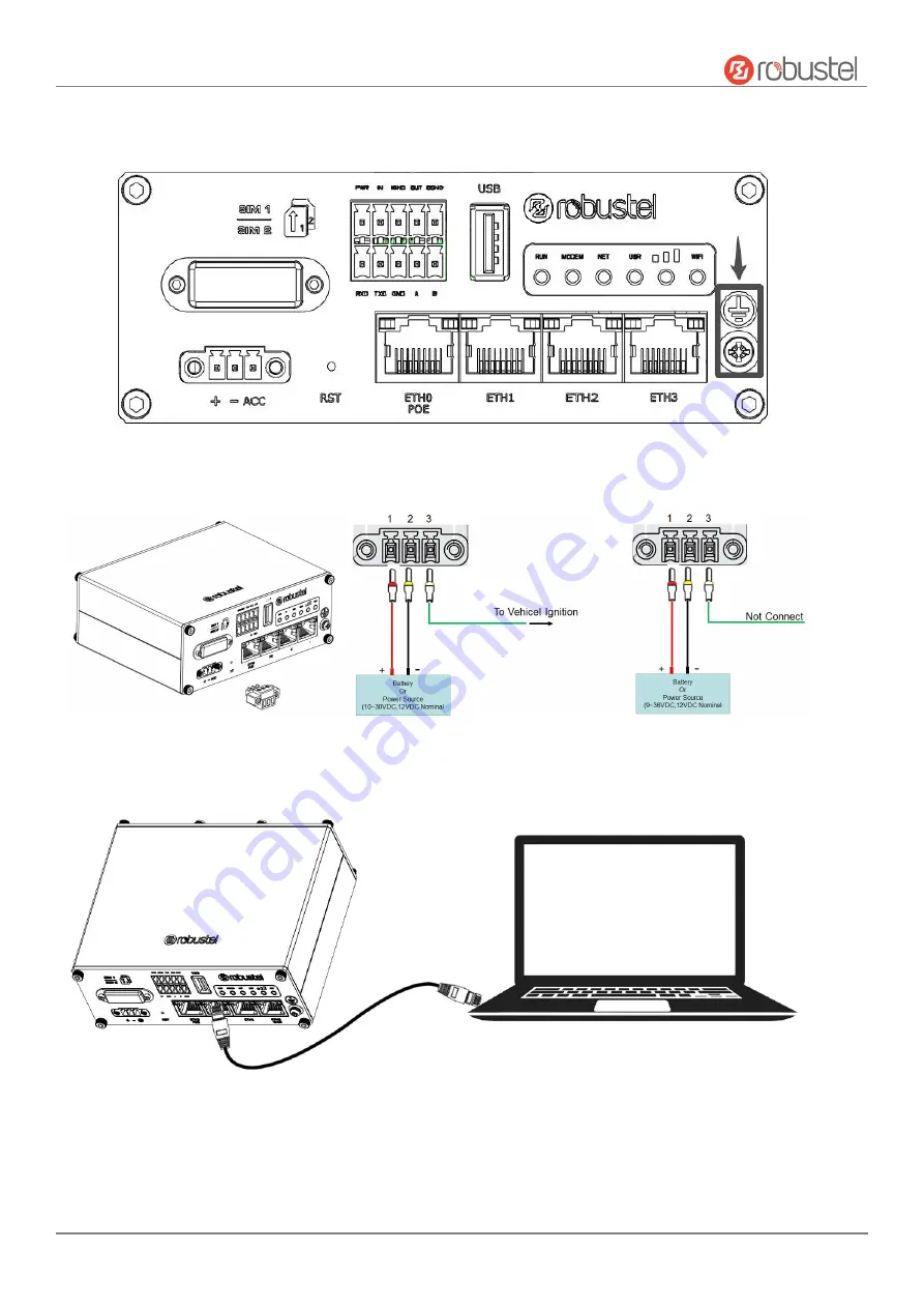
5. Grounding the Device.

Grounding will help to prevent the noise effect due to electromagnetic interference

(EMI). Connect the device to the site ground wire by the grounding screw before powering on.

6. Power Supply installation.

Insert the power supply cord into the corresponding terminal block if needed,

then insert the terminal block into the power connector.

7. Connect the Router to a Computer.

Connect an Ethernet cable to the port marked ETH1~ETH3 at the front of

the R2110 Router, and connect the other end of the cable to your computer.

Summary of Contents for R2110

Page 1: ...Robustel R2110 Hardware Manual RT044_HM_R2110 1 11 R2110 Hardware Manual Version 1 0 0 Date Aug 03 2022...

Page 2: ...parts in concentrations above the limits defined by SJ T 11363 2006 SJ T 11364 2014 The electronic industry standard of the People s Republic of China SJ T 11364 2014 Labeling Requirements for Restri...

Page 3: ...DD B38 B39 B40 B41 3G WCDMA B1 B2 B4 B5 B6 B8 B19 2G GSM B2 B3 B5 B8 Oceania EMEA 4G LTE FDD B1 B3 B8 B18 B19 B26 LTE TDD B41 Japan Name of the Part Hazardous Substances Pb Hg Cd Cr VI PBB PBDE DEHP B...

Page 4: ...evelopment Canada s licence exempt RSS s Operation is subject to the following two conditions 1 This device may not cause interference 2 This device must accept any interference including interference...

Page 5: ...l support robustel com Web www robustel com Document History Updates between document versions are cumulative Therefore the latest document version contains all updates made to previous versions Date...

Page 6: ...ons Package Checklist Before commencing installation ensure your package has the following components Device 3PIN Terminal Block 2x5PIN Terminal Block RCMS Card Quick Start Guide Card Cellular Antenna...

Page 7: ...d received Off Link connection is not working NET Green On solid Connection to 4G network is established On blinking Connection to Legacy network 3G or 2G is established Off Network is not joined or j...

Page 8: ...Connection is not established 5 Digital IO Serial Port 2x5PIN 3 5mm pitch terminal block 1 set of DO 1 set of DI 1 x RS232 and 1 x RS485 DI signal access can be used for NPN PNP type sensor signal or...

Page 9: ...r 2 Antenna Installation Rotate the antenna into the antenna connector accordingly Here take the cellular antenna as example 3 Terminal Block Installation Insert the terminal blocks into the interface...

Page 10: ...ground wire by the grounding screw before powering on 6 Power Supply installation Insert the power supply cord into the corresponding terminal block if needed then insert the terminal block into the p...

Page 11: ...information shown in the product label when prompted for authentication w 5 After logging in the home page of the web interface is displayed then you can view system information and perform configura...

Reviews: