Robust Sweet 16 Owner'S Manual Download Page 4


41.


GROUNDING INSTRUCTIONS:

  In the event of a malfunction or breakdown, grounding provides a 

path of least resistance for electric current to reduce the risk of electric shock. You lathe is 
equipped with an electric cord having an equipment grounding conductor and a grounding plug. 
The plug must be plugged into a matching outlet that is properly installed and grounded in 
accordance with all local codes and ordinances. 
 
Do not modify the plug provided – if it will not fit the outlet, have the proper outlet installed by a 
qualified electrician. Improper connection of the equipment‐grounding conductor can result in a 
risk of electric shock. The conductor with insulation having an outer surface that is green with or 
without yellow stripes is the equipment‐grounding conductor. If repair or replacement of the 
electric cord or plug is necessary, do not connect the equipment‐grounding conductor to a live 
terminal. Check with a qualified electrician or service personnel if the grounding instructions are 
not completely understood, or if in doubt as to whether the tool is properly grounded. Use only 3‐
wire extension cords that have 3‐prong grounding plugs and 3‐pole receptacles that accept the 
tool’s plug. Repair or replace damaged or worn cord immediately. 
 
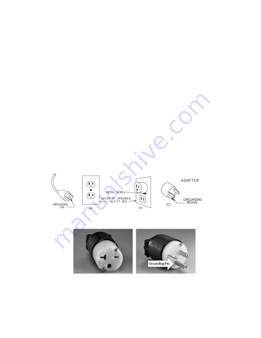
Lathes wired to run on 110‐120 volt circuits are intended for use on a circuit that has an outlet 
(NEMA 5‐15) that looks like the one illustrated in Sketch A in the figure below. The tool has a 
grounding plug that looks like the plug also illustrated in the figure.  A temporary adapter, which 
looks like the adapter illustrated in Sketches B and C, may be used to connect this plug to a 2‐pole 
receptacle as shown in Sketch B if a properly grounded outlet is not available. The temporary 
adapter should be used only until a properly grounded outlet can be installed by a qualified 
electrician. The green‐colored rigid ear, lug, and the like, extending from the adapter must be 
connected to a permanent ground such as a properly grounded outlet box. 


Lathes wired for operation on a 220‐240 volt circuit are intended for use on a circuit that has an 
grounded outlet and plug that looks like those illustrated below (NEMA 6‐20).   


*** SAVE THESE INSTRUCTIONS ***


Summary of Contents for Sweet 16

Page 1: ... on the inverter to run the lathe Use the magnetic backed controller When plugged in the display will read Stop When running the spindle RPM is displayed Your inverter may be beige or blue Both work the same For safety sake turn the speed dial to the lowest setting every time you start the lathe This is a great habit to get into Robust Tools LLC 101 Business ID Barneveld Wisconsin 53507 Please rea...

Page 2: ... a safe distance from work area 10 MAKE WORKSHOP KID PROOF with padlocks master switches or by removing starter keys 11 DON T FORCE TOOL It will do the job better and safer at the rate for which it was designed 12 USE RIGHT TOOL Don t force tool or attachment to do a job for which it was not designed 13 USE PROPER EXTENSION CORD Make sure your extension cord is in good condition When using an exte...

Page 3: ...to a complete stop 29 MAKE ALL ADJUSTMENTS WITH POWER OFF Do not make adjustments when the lathe or work piece is turning Make all adjustments with power off 30 TIGHTEN ALL CLAMPS BEFORE OPERATING LATHE All clamp handles on the banjo toolrest tailstock and auxiliary equipment should be tightened before operating lathe 31 CHECK THE WORKPIECE CAREFULLY for splits knots or other obstructions which ma...

Page 4: ...s are not completely understood or if in doubt as to whether the tool is properly grounded Use only 3 wire extension cords that have 3 prong grounding plugs and 3 pole receptacles that accept the tool s plug Repair or replace damaged or worn cord immediately Lathes wired to run on 110 120 volt circuits are intended for use on a circuit that has an outlet NEMA 5 15 that looks like the one illustrat...

Page 5: ...s are wired for 220V An isolated 220VAC 20 amp circuit is required Wiring and outlets should adhere to local electrical codes Lathes wired for 110 1 5HP only should be on a dedicated 110 volt 20 amp circuit Avoid using extension cords Required 220 Volt NEMA 6 20 Receptacle If you are in doubt about the power connection seek advice from a qualified electrician Lathe Height Most turners like to adju...

Page 6: ...your lathe from running properly if at all Other settings such as ramp up and ramp down speeds can be set to your liking It is strongly recommended not to change any parameters until you are very familiar with your lathe If you are unhappy with your changes contact Robust Tools for the default parameters VFD aka inverter located on the side of the headstock Pendant Controller The corded pendant co...

Page 7: ...huck onto the spindle threads Some turners like to use a spindle washer before installing a faceplate or chuck 4 Push the Spindle Lock Knob down to release the spindle Lathe Spindle Some faceplates and chucks are equipped with a set screw to secure them to the spindle Before tightening this set screw ensure that it lines up with the groove provided on the spindle Using the Spindle Index The spindl...

Page 8: ...est Spin the work by hand before starting to make sure all parts of the work piece clear the toolrest Gouges and chisels should remain on the toolrest whenever the tool is in contact with the work piece Remove the toolrest when sanding or polishing so fingers do not get pinched Using the Banjo and Toolrest American Beauty shown S16 operates the same Tailstock Operation To move the tailstock along ...

Page 9: ...To remove it tap the handwheel end of the spindle with a block of wood You can also screw two of the cap screws into the threaded jack screw holes in the boss to push the spindle assembly out You may need to clean debris from the holes first 7 Remove the old belt and replace with new belt 8 If you used jack screws to extract the spindle now is the time to remove them from the bearing boss 9 Clean ...

Page 10: ...ed anymore tension on the belt than you can apply by hand Do not use a lever on the motor or pulley to increase tension Doing so just puts needless stress on the motor bearings and will lead to their premature failure Optional Vacuum Adapter The vacuum adapter simply slips into the spindle on the handwheel end Some lubricant on the O rings makes this process easier and extends the life of the O ri...

Page 11: ... is normal DRIVE CENTER The cup style drive center is perfect for safely driving spindles and small bowls To use it tap it into the wood before mounting If you get a catch the wood just spins on the center Like our Live Center the tip is adjustable and reversible The Bowl Drive threads onto the cup center and provides more surface area for driving larger work BOTH CENTERS The contact rings of the ...

Page 12: ...ve center or other accessory from the extension Reversing the Banjo To reach across the gap it is sometimes beneficial to reverse the banjo The banjo can be reversed by unscrewing the black handle near the tool rest and threading it into the other end As mentioned previously the toolrest clamp can also be reversed In some cases you may want to use the optional Tool Rest Dog Leg to get out over the...

Page 13: ...d Then slide the tailstock so that the large keeper washer underneath the tailstock is centered on the gap between the lathe bed and gap bed Tighten the tailstock and then tighten the nuts on the hanger studs 5 When reinstalling the gap bed be sure the mating surfaces are clean HINT Watch the video on our website where this is demonstrated Be sure to tighten the bolts or nuts on the gap bed regard...

Page 14: ...et the lathe settle to your floor conditions Go back and tighten the bolts you loosened Your lathe should now be sitting with its weight evenly distributed on each foot Having the lathe sitting evenly on the floor is more important than having the lathe perfectly level Hard rubber pads are also provided Put one under each foot after you have the lathe positioned Optional Tilt Away Follow the insta...

Page 15: ... the ball joints The threaded studs must point towards the back of the lathe on both bars Also when attaching the ball joints to the frame the wrench flats should be vertical Raise casters before turning Using the Casters Press down on the handle to engage the casters Pull up on the handle to disengage Casters lowered for moving the lathe Casters raised when turning Ball Joint threaded stud must p...

Page 16: ...own for no apparent reason while you are making cuts or turning out of balance work but you can start it right back up your spindle lock probably needs adjusting See above ALIGNMENT If your centers are out of line look for debris stuck to the bottom of the tailstock A very small amount can make a big difference If a thorough cleaning does not re establish alignment go through the settling procedur...

Page 17: ...ill and clean and lubricate the mechanism Spray grease is handy for the threads and inside of the quill hole Sometimes burrs will form along the groove that the spindle lock rides in It doesn t take much of a burr to cause the quill to bind Take a small file and remove the burr Filing a small chamfer on the edge of the groove is also a good idea LATHE MAINTENANCE TOOL KIT Here are a few things to ...

Page 18: ... and tear improper repair alterations or lack of maintenance Robust lathes are designed to turn wood Working with other materials may void the warranty Robust Tools LLC makes no other warranty express or implied No agent representative distributor dealer or employee of Robust Tools LLC has the authority to increase or otherwise change the obligations or limitations of this warranty The obligations...

Reviews: