Commissioning
28
4
4
COMMISSIONING
Before commissioning the system, check that the plumb-
ing system and electrical installations are complete in re-
lation to the information contained in sections 1
p. 6,
2
p. 9 and 3 p. 20 of this manual.
The K18 and auxiliary boiler (if present) may start
during and at the end of commissioning. Make
sure that the plumbing system is complete and
filled with water.
Commissioning must be done by a TAC.
4.1
USING THE QAA74.611 ADVANCED
ROOM UNIT'S INTERFACE
The QAA74.611 room unit is also used for configuring and
adjusting the System controller for the K18.
This paragraph explains how to operate on the user inter-
face of the device at the Engineer user level; this will allow
you to perform all checking and parameters change oper-
ations required for the commissioning and optimisation
of the system, briefly described in the following part of
this Installation manual.
The System controller User manual contains a more struc-
tured description of the room unit and of the operations
available to the end user; for the technical staff, involved
in the installation or in technical support of the product,
the information contained in the User manual is useful
and complementary to those contained in this document.
The user interface of the room unit consists of a backlit
monochrome display and a knob that can be turned and
pressed.
4.1.1
Access to complete parameter list at
Engineer user level
Proceed as follows:
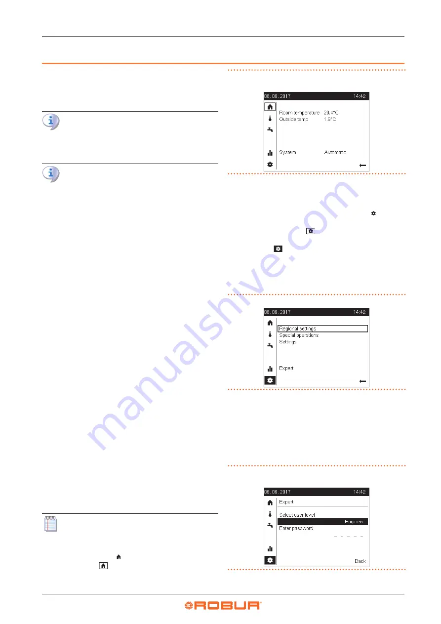
1. When the device is turned on, check that the display
appearance looks like Figure 4.1
p. 28, which is an
example of the start page.
If the display looks different, simply press and hold the
knob for a few seconds: the device will automatically
move to the start page.
Sometimes also, i.e. immediately after powering up the
system, the display may show the message Operator
unit being refreshed together with a progress indica-
tion of the operation. In this case, wait a few minutes
for the operation to complete, then proceed as above
to the start page.
The start page may show some different infor-
mation from the example in Figure 4.1
depending on your system configuration. That is
quite normal. The important thing is that the dis-
play shows the symbol (start page identifier)
framed, i.e. . The frame around the symbol indi-
cates that the symbol is preselected: the start page
is shown on the display but not accessed.
Figure 4.1
Start page example, for a device configured as room
unit
2. Turn the knob clockwise: the frame will move in se-
quence to enclose the symbols placed vertically below
that of the start page and, at the same time, the page
showed will change. Turn to enclose the symbol,
which identifies the device settings page. This symbol
will then be shown as .
3. Press the knob: the symbol is then selected and shown
in negative . The configuration settings page, which
already appeared by following step 2 above, is ac-
cessed and looks like Figure 4.2
enclosing the first editable field (Regional settings)
inside the page.
Figure 4.2
Device setting page
4. Turn the knob clockwise until the Expert field is
framed, then press the knob to access the user level
selection page. The value of the field indicating the
current user level is framed (preselected).
5. Press again the knob to select the field, then turn it to
change its value to Engineer; at the end of this step,
the display looks like Figure 4.3
Figure 4.3
User level selection page with user level set to
Engineer
6. Press the knob to confirm the setting, then turn the


