background image

Robotiq FT-150/300 Sensor

Instruction Manual

Robotiq inc. © 2016

43

7.  

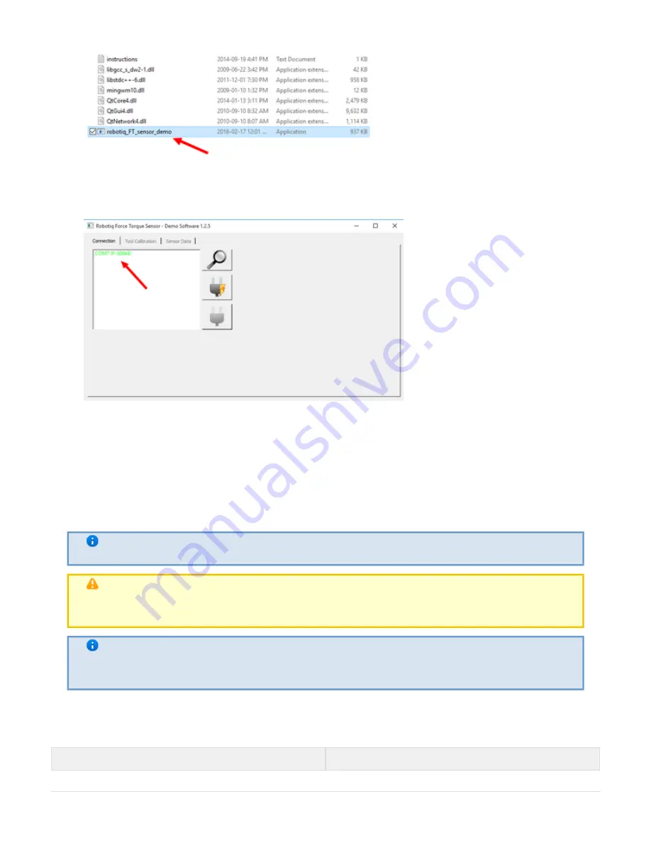
8.  You should see a COM port in green with a serial number, showing the Sensor connected to the PC. Click on

it.

By going into the "Sensor Data" tab, you can now see in real time the force and moment applied on the FT Sensor.

4.6 Serial communication

The FT Sensor uses two communication modes, Modbus RTU and data stream. The Modbus RTU communication
mode is used to obtain information on the Sensor, like its firmware version. The data stream mode is used to obtain
data from the Sensor.

Info
It is recommended to use the FT Sensor data stream to obtain faster data acquisition.

Note

Modbus RTU can be used to obtain data, but will result in a slower data acquisition frequency.

Info

In both modes, force and torque data from the Sensor will be in 

16-bits signed integer format.

Modbus RTU:

The Modbus RTU serial communication configuration parameters are:

Parameter

Value

Summary of Contents for FT 150

Page 1: ...1 ROBOTIQ INC 2016 Get the latest version of the manual at support robotiq com...

Page 2: ...age 24 4 1 1 Linux 26 4 1 2 Windows 28 4 2 ROS 30 4 3 Universal Robots driver package 31 4 3 1 Installing and testing 32 4 3 2 Provided examples 34 4 3 3 Custom programs 34 4 4 ActiveDrive toolbar for...

Page 3: ...ice when necessary due to product improvements modifications or changes in specifications If such modification is made the manual will also be revised see revision information See the latest version o...

Page 4: ...are physically different but the concept of utilization and the software provided by Robotiq is the same for both products The following manual instructions apply to both versions unless explicitly s...

Page 5: ...e 150 N 300 N 15 N m 30 N m Similitude Feature FT 150 FT 300 Effective resolution 0 2 N 0 02 N m Cross talking None External noise sensitivity Immune Overload capacity 500 Input Voltage 24 V DC Maximu...

Page 6: ...ch the robot not Info Details on the bolt pattern and indexing pin for the tool side and the robot side can be found in the specification section The screw positioning for the coupling and the robot m...

Page 7: ...gs are meant to install the FT Sensor on various robot models see available models Sensor Cable is used for power and communications with the FT Sensor and is available in different lengths Mechanical...

Page 8: ...operations on the FT 150 or FT 300 and associated robot or tools Installation Control Maintenance Inspection Calibration Programming Decommissioning This documentation explains the various components...

Page 9: ...or human robot collaboration Warning The Sensor needs to be properly secured before operating the robot Do not install or operate a Sensor that is damaged or lacking parts Never supply the Sensor with...

Page 10: ...llation on a robot or other automated machinery or equipment Note Always comply with local and or national laws regulations and directives on automation safety and general machine safety The unit may...

Page 11: ...ble CBL PWR 2054 10 USB Signal Converter ACC ADT USB RS485 USB Signal Converter ACC ADT USB RS485 Options Couplings Note Coupling is optional for the FT 150 but mandatory for the FT 300 Adapter plates...

Page 12: ...environmental conditions FT 150 FT 300 Minimum storage transit temperature 25 C Maximum storage transit temperature 70 C Minimum operating temperature 15 C Maximum operating temperature 35 C Humidity...

Page 13: ...section Spare Parts Kits and Accessories section Note The FT 300 coupling is mandatory you can customize yours from a blank provided by Robotiq Here are the steps to follow for the installation of the...

Page 14: ...not included with the Sensor POWER SUPPLY SPECIFICATIONS FT 150 FT 300 Output voltage 6 to 24 V DC 5 to 24 V DC Max power consumption 2 W 2 W Overcurrent 1 A Fuse Phoenix 0916604 UT6 TMC M 1A Overvol...

Page 15: ...tacle Sensor side and connector cable side with associated pinout The M12 5 pin A coded connector is used in accordance with IEC 61076 2 101 Both versions of the Sensor share the same M12 5 pins male...

Page 16: ...Kits and Accessories section Figure 3 5 1 1 and the following directions GND 0V is wired to Sensor pin 1 as stated in Section 3 5 The converter will provide you with a standard USB 2 0 male A connect...

Page 17: ...ring must respect Spart Parts Kits and Accessories section Figure 3 5 2 1 Warning Do not wire converter pin 3 5V on the RS485 The 24V power supply is supplied via the converter NOT The converted side...

Page 18: ...for Not doing so will significantly affect the sensor signal How does it work The procedure requires moving the robot in three configurations for which each orientation of the tool is different Using...

Page 19: ...ual Robotiq inc 2016 19 2 Run the program Follow the instructions on the pop ups The displayed instructions explain how to move the robot through the three different poses In each case make sure that...

Page 20: ...Robotiq FT 150 300 Sensor Instruction Manual Robotiq inc 2016 20 3 You can now monitor the forces in the Variables tab...

Page 21: ...bration procedure for the Visual Demo Software PC Info You need the Visual Demo Software installed first see for download and installation Section 4 5 To calibrate your FT Sensor Go to the Tool Calibr...

Page 22: ...own in Figure 3 6 1 On the FT 150 Sensor the LED is located on the Sensor next to the cable connector COLOR LED STATE INFORMATION off No power Blue red on FT 150 Sensor is booting Blue on FT 150 Senso...

Page 23: ...Robotiq FT 150 300 Sensor Instruction Manual Robotiq inc 2016 23 Blue on FT 300 Sensor is functional communication established Figure 3 6 1 FT Sensor status LED...

Page 24: ...the use of serial communication in generic applications Section 4 6 The following table represent compatibility of our various software packages on Universal Robots Package CB1 CB2 CB3 CB3 1 FT Sensor...

Page 25: ...of its contributors may be used to endorse or promote products derived from this software without specific prior written permission THIS SOFTWARE IS PROVIDED BY THE COPYRIGHT HOLDERS AND CONTRIBUTORS...

Page 26: ...opened This section of code can be modified by the user if necessary to avoid the scanning of ports for example if another device would become confused when receiving a message that it cannot underst...

Page 27: ...Mx My Mz format Figure 4 1 1 1 Sensor Data Acquisition Adapt to a User Application In practice the provided source code will be adapted to either be incorporated with a custom application or to commun...

Page 28: ...e sensor driver using Make Procedure to Compile and Test the Provided Source Code This procedure explains how to install MinGW compile the provided source code and verify that the sensor data is prope...

Page 29: ...a custom application or to communicate with one At this point the main c file should be adapted according to the suggested comments inserted in the code Please note that Robotiq can only support our...

Page 30: ...s org ROS Tutorials InstallingandConfiguringROS Environment 2 Checkout the in the src folder robotiq_force_torque_sensor package 3 Go back into the workspace root and execute the following command in...

Page 31: ...ery easily integrated with Universal Robots using the software package described in this section Once installed the sensor readings will be available in Polyscope and will be directly usable in the ro...

Page 32: ...4 The Robotiq Force Torque Sensor software package can be downloaded at support robotiq com Extract the content of the zip file onto a blank USB flash drive Plug the flash drive into a USB port for t...

Page 33: ...outed to the Universal Robots control box Remember to practice good cable management and allow enough flexibility in your cable lines According to the wiring section of this manual connect the the pow...

Page 34: ...olerance on the force lecture minimum is 0 5 N so a noise level under 1 N will result in erratic results In this example 2 5N is used because the sensor and the tool cables can have an effect on the s...

Page 35: ...o zero before applying measuring force or torque Use the rq_set_zero subprogram when no force is applied on the sensor and with the same orientation you want to use for further readings 4 4 ActiveDriv...

Page 36: ...ome status information while the software package is automatically installing Do not unplug the flash drive until the operation has been completed When a green USB text appears then unplug the USB dri...

Page 37: ...Tap to start or stop ActiveDrive ActiveDrive will automatically turn off after 30s of inactivity When initiated ActiveDrive allows you to move the robot freely by applying force on robot s end effect...

Page 38: ...tion speed control is toggled between fast and slow allowing precise movement in slow motion The Force Torque Sensor will switch to slow speed automatically whenever high forces are detected for examp...

Page 39: ...and press Zero Sensor to start ActiveDrive When the speed setting of the robot is lower than 50 ActiveDrive has stopped because the robot s speed setting is lower than 50 Please adjust the speed setti...

Page 40: ...Force Torque Sensor is connected properly and that its driver is installed on the robot If the robot is not properly initialized ActiveDrive cannot start because the robot is not initialized If a pro...

Page 41: ...iveDrive If the speed setting of the robot is lower than 50 ActiveDrive cannot start because the robot speed setting is lower than 50 Please adjust the speed setting and try again If the Free Drive bu...

Page 42: ...ion 3 6 2 for the calibration procedure Software Package Installation Make sure that you have the latest version of the Visual Demo Software which can be found at support roboti q com Copy all the fil...

Page 43: ...U and data stream The Modbus RTU communication mode is used to obtain information on the Sensor like its firmware version The data stream mode is used to obtain data from the Sensor Info It is recomme...

Page 44: ...am Data stream mode is the recommended method of obtaining data from the Sensor Once initiated the Sensor will stream force and moment data continuously until communication is interrupted by the user...

Page 45: ...ns The following sections provide data on the various specifications of the Robotiq Force Torque Sensor Section 5 1 details the technical dimensions of the sensor Section 5 2 details the mechanical sp...

Page 46: ...Robotiq FT 150 300 Sensor Instruction Manual Robotiq inc 2016 46 Figure 5 1 2 Robotiq FT 300 Sensor general technical dimensions Info Reminder Measures in millimeters...

Page 47: ...ool side of the Sensor Both indexing pins are M3 dowel pins press fitted into the Sensor Note M3 dowel pins are normally pressed onto the FT 150 sensor when delivered If press fitting of the M3 dowel...

Page 48: ...dowel pin is slip fitted and 6 mm deep Outside diameter of the flange is 64 mm and inside is 45 mm Note Sensor tool flange must only make contact with the end effector tool flange within the 45 to 64...

Page 49: ...for M6 dowel pin has a tight fit H7 and 6 mm deep Outside diameter of the flange is 64 mm and inside is 45 mm Info FT 300 tool side bolt pattern matches ISO 9409 1 50 4M6 Figure 5 1 2 2 FT 300 Sensor...

Page 50: ...7 5 mm 37 5 mm IP rating 541 43 Stiffness F F x y 3 2 X 10 N m 6 Fx Fy X 106 N m Fz 3 9 X 10⁶ N m Fz X 106 N m M M x y 4700 Nm rad Mx My Nm rad Mz 4600 Nm rad Mz Nm rad 1 Expected rating certification...

Page 51: ...igure 5 1 1 Info All values are approximate Actual coordinates may vary according to various options present on the Sensor Here is the approximate position of the center of mass for the FT Sensor Coor...

Page 52: ...talking None 2 Drift Force 3 N over 24h Torque non significant non significant Data output rate 100 Hz Temperature compensation 15 to 35 C 1 For example welding current passing through the Sensor hole...

Page 53: ...CATION FT 150 VALUE FT 300 VALUE Input voltage 6 to 28 V DC 10 5 to 24 V DC 10 Max power consumption 2 W Communication electrical interface RS 485 Recommended fuse Phoenix 0916604 UT6 TMC M 1A Recomme...

Page 54: ...7 Spare Parts Kits and Accessories The following sub sections contain data required for custom couplings or creating couplings from blanks Info All Robotiq couplings and adapter plates are provided wi...

Page 55: ...obot side fixing Spare part list number is FTS CPL BLANK Figure 5 5 1 1 Technical dimensions of the blank coupling for the FT 150 Figure 5 5 1 2 schematics represent the optional blank coupling for th...

Page 56: ...Robotiq FT 150 300 Sensor Instruction Manual Robotiq inc 2016 56 Figure 5 5 1 2 Technical dimensions of the blank coupling for the FT 300...

Page 57: ...the program routine This will compensate for the tool weight for its current orientation the effect of the attachment mechanisms on the Sensor and any other factors which could affect the readings It...

Page 58: ...g 50 4M6 1D6 Coupling for 50 mm PCD 1 4 M6 thread and 1 6 mm M6 indexing pin To be used on UR robots FTS CPL 103 150 FTS 300 CPL 062 Coupling 40 4M6 1D6 Coupling for 40 mm PCD 1 4 M6 thread and 1 6 mm...

Page 59: ...t the provided USB 485 converter to a USB port of a Windows PC In the Windows PC open the Device Manager You should see a USB Serial Port device in the Ports COM LPT category If not it is possible tha...

Page 60: ...ded to have a software offset which compensates for these variations in addition to the effort caused by the tool weight for a given orientation It is preferable to set the software offset before star...

Page 61: ...ble for damages resulting from the use of the product nor shall be responsible for any failure in the performance of other items to which the product is connected or the operation of any system of whi...

Page 62: ...Robotiq FT 150 300 Sensor Instruction Manual Robotiq inc 2016 62 St Nicolas Qc G7A 2N1 Canada Comments...

Reviews: