background image

10


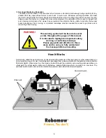
Wires leading from the perimeter 

to the Perimeter Switch are 

adjacent and touching.

Indoor Power 

Supply

Zone A

The Perimeter Switch MUST be 

mounted 

vertically

in order 

to maintain its’ water resistance

Wires leading from the perimeter 

to the Perimeter Switch are 

adjacent and touching.

Indoor Power 

Supply

Zone A

The Perimeter Switch MUST be 

mounted 

vertically

in order 

to maintain its’ water resistance

Chapter 1 - Perimeter Wire Setup 


1.1 Preparations 


Read carefully the Operating and Safety Manual prior to setup.


It is recommended to mow your lawn using a conventional lawn mower and water the ground before 
starting the setup for easier driving of the pegs.


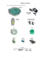
Confirm all parts for the setup are included (refer to ‘What’s in the Box’ page 9).


During the setup you will also need the following tools: 


1.2 Planning the Setup  


1.2.1 

Perimeter Switch Location 

  Find a convenient spot 

outside the perimeter

, but a location that is relatively easy for you to 

access. 

  The Perimeter Switch must be 

mounted vertically

 in order to maintain its’ water resistance and 

preferably in a 

dry and sheltered location

.  


Close to a wall socket

 (230V/120V) – as it is connected to an indoor Power Supply. 


1.2.2 

Placing the Perimeter Switch 

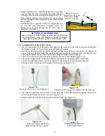
  The Perimeter Switch connector is designed for quick and easy 

disconnection that allows you to easily move the perimeter switch 
between plots. 

  The Perimeter Switch also comes with a large stake that 

fastens to its back, making transfer from one plot to 
another easier by allowing you to disconnect the switch 
and move it with the stake still attached (Figure 1.3).  

Hammer 

Combination 

Pliers

Small flat and 

Philips screwdrivers 

Figure 1.1 

– Tools required for the setup

IMORTANT INFORMATION! 

Before starting the setup, it is necessary to first 

read this chapter in order to be aware of all setup rules and instructions so you are able 
to determine the best location for the Perimeter Switch and the perimeter wire layout. 

Figure 1.2


Perimeter Switch  

Location

Figure 1.3 

- Perimeter 

Switch with stake attached 

Summary of Contents for RM200

Page 1: ...Operating Safety Manual RM200 www robomow eu www robomow com DOC5202E ...

Page 2: ...ners Welcome to the world of home robotics with the Friendly Robotics Robomow Thank you for purchasing our product We know that you will enjoy the extra free time you will have while using Robomow to mow your lawn When set up and used properly Robomow will operate safely on your lawn and provide you with a quality of cut matched by a few mowers of any kind You will be impressed with your lawn s ap...

Page 3: ...Mowing 25 3 2 Scanning Mowing of the inner area 25 3 3 Skipping Edge Mowing 25 3 4 Operation 25 3 5 Completing the Operation 25 3 6 Charging 26 Chapter 4 Text Messages and Troubleshooting 27 4 1 Messaging 27 4 2 Other Operational or Fault Problems 31 Chapter 5 Maintenance and Storage 33 5 1 Recommended Maintenance Schedule 33 5 2 Cleaning 33 5 3 Battery 33 5 4 Replacing the Blade 34 5 5 Splicing t...

Page 4: ...achments designed for this product Operation 13 Caution Do not touch rotating blade 14 Remove the fuse whenever Robomow starts vibrating abnormally or after striking an object 15 Never let Robomow operate without supervision 16 When using the Remote Control mow only in daylight or in a good artificial light 17 Do not operate Robomow using the Remote Control when barefoot or wearing open sandals Al...

Page 5: ...damage the eyes or skin 43 Wear eye protection and use gloves when setting the perimeter wire and driving the wire stakes pegs Firmly drive all pegs in order to keep the wire from becoming a tripping hazard 44 Do not use the power supply charger if the cord has damaged 45 A spark may be created when inserting the fuse to the robot Therefore it is forbidden to perform these tasks close to flammable...

Page 6: ... machine when operating Keep people in particular children pets and bystanders away from the area in which Robomow is being used 5 Severing of toes or fingers Rotary mower blade Risk of injury from rotating cutting blade Keep hands and feet away and do not attempt to lift Robomow from this area 6 Remove the Fuse before working on or lifting Robomow Remove the Power Pack before working on or liftin...

Page 7: ...during operation will stop all mower movement and stop the rotation of the blade immediately 1 second 7 Batteries Fuse Located below the bumper cover on the left side of Robomow Removing the battery fuse will prevent any operation of the Robomow It is required to remove the fuse before lifting Robomow and before any maintenance is done 8 Two Step Operator Presence Control While in manual mode usin...

Page 8: ... from moving How It Works A small wire called the perimeter wire is placed around the perimeter of the lawn and any other areas where you do not want the mower to enter A small signal is generated from a device attached to the perimeter wire called the Perimeter Switch When turned on this signal is carried through the perimeter wire creating what we define as a virtual wall The virtual wall is vis...

Page 9: ...ly for charging Robomow Perimeter Switch Indoor Power Supply for Perimeter Switch What s in the Box Open the box and lift the Robomow from its carrying handle RoboRuler Robomow Plot Connector Wire Connector Charging Adaptor ...

Page 10: ...a location that is relatively easy for you to access The Perimeter Switch must be mounted vertically in order to maintain its water resistance and preferably in a dry and sheltered location Close to a wall socket 230V 120V as it is connected to an indoor Power Supply 1 2 2 Placing the Perimeter Switch The Perimeter Switch connector is designed for quick and easy disconnection that allows you to ea...

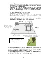
Page 11: ... set Chapter 2 1 1 When this area is completed drive the mower back for re charging Determining the distance between adjacent perimeter wires 1 If lawns are installed by the same perimeter wire that is connected to the same source Base Station Perimeter Switch then it is enough to keep a distance of one meter between the wires to prevent interference in operation 2 If lawns are installed using dif...

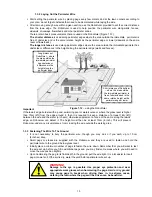
Page 12: ... Figure 1 7 Figure 1 6 Option B Separated zones where grass areas are not contiguous Distance between wires greater than 1 meter 3 ft Perimeter Switch Zone A Zone A Zone B Figure 1 7 Multiple areas with narrow passes Narrow Pass At least 1m 3ft between wires so Robomow can effectively navigate through in order to move between the two areas while mowing the lawn When area width between perimeter wi...

Page 13: ...d closely together should be covered by a single perimeter island or if they are close to the edge of the lawn leave them out of the designated area 1 2 5 Slopes The Perimeter Wire should not be laid across a slope that is steeper than 15cm 6in per distance of 1 meter 3 3ft 15 There is a risk that Robomow will find it difficult to turn and might cross the wire outside especially in damp weather co...

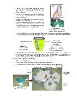
Page 14: ... The plastic covering is designed as a dispenser for the wire so do not remove the wire spool from the covering Peg the beginning of the wire to the ground where the Perimeter Switch will be located be sure to leave spare wire to close the loop at the end of the setup Figure 1 11 Lay the wire from the Perimeter Switch to the lawn Start laying the wire to the counterclockwise direction when standin...

Page 15: ...e so Robomow can detect it The height must then be at least 15cm 6 inch This will prevent Robomow under any circumstances from crossing the wire outside the working area 1 3 3 Fastening The Wire To The Ground It is not necessary to bury the perimeter wire though you may do so if you wish up to 10 cm 4 inches deep Small pegs or stakes are supplied with the Robomow and they are used to fasten and ho...

Page 16: ...rds the Perimeter Switch location use the same pegs to attach the two wires from the lawn to the Perimeter Switch location There are two loose wire ends where the perimeter wire set up was started Figure 1 14 Use the same peg to fasten these two perimeter wire ends down to the ground and twist them Cut the wire end without the connector so they are of equal length removing any excess wire Strip ba...

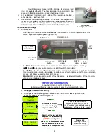
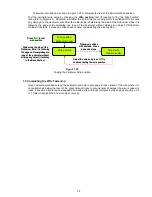
Page 17: ...ext to the ON button indicates that the system is on and functioning properly The Perimeter Switch also has indicators for a disconnected broken perimeter wire and for poor wire splicing Figure 1 19 The Perimeter Switch has an automatic shutoff feature eliminating the need for you to turn it off after each use It will shut itself off after 12 hours of operation You may manually turn the perimeter ...

Page 18: ...a small plastic bag attached to the Robomow located under the Bumper Cover Lift the Bumper Cover and insert the fuse The fuse can be inserted in either direction See figure 1 22 Robomow will now power up wake up The Batteries are charged at the factory and have plenty of power to perform the initial setup and test run However after the initial set up process is completed the batteries need to be c...

Page 19: ... Station Follow the instructions as shown in figure 1 25 to complete the test of the Perimeter Wire position Test the perimeter wire setup by choosing the Wire position test If required to find the Wire position menu refer to Figure 2 1 Robomow will follow the wire while the mowing motor is switched off to prevent any damage to the perimeter wire after the initial setup Walk along the side of the ...

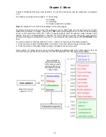
Page 20: ...es to and features that can be enabled disabled Pressing the STOP button at any time during the menu selection process will bring you one step back in the menu To scroll between the submenus use the UP DOWN arrow keys To see the main menu functions options 2 1 to 2 4 Figure 2 1 follow one of the following options 1 When the mower is out of the Base Station scroll down to the User options display a...

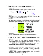
Page 21: ...the STOP key to unlock the controls Two minutes of inactivity will re lock the keys It is strongly recommended to use the Child Guard menu option in order to prevent operation by children or others who are not familiar with the safe operation of the Robomow 2 2 2 Anti Theft The anti theft system provides the user a disabling function that will prevent anyone from using or driving the Robomow unles...

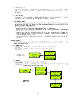
Page 22: ...actual reading of the rain sensor Rain sensor on off Allows turning the rain sensor feature off to enable operation in rain and wet grass conditions 2 2 5 Language Allows the user the option of viewing the LCD text in several different language versions 2 2 6 ECO Mode The ECO Economic mode feature enables operating Robomow using minimum energy required to cut the grass and maintain the lawn The EC...

Page 23: ...e wire is completed 2 2 10 Delay operation This option allows the user to press GO but delay the operation starting time It is useful when you want to start the operation later in the day when the grass is dry and not early in the morning when the grass is wet and you have to leave for work To use this option follow the steps below Set the Delay operation to X hours choose between 1 2 3 or up to 8...

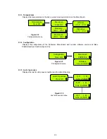
Page 24: ...nfiguration Press GO Configuration Press GO Main board ESB5000E Software 5 4v 21 10 07 Configuration Press GO Configuration Press GO Configuration Press GO Configuration Press GO Main board ESB5000E Software 5 2v 21 10 07 Last stop causes Press GO 1 11 3 10 35 25 05 08 2 20 2 11 24 24 05 08 10 7 6 10 58 19 04 08 Last stop causes Press GO Last stop causes Press GO Last stop causes Press GO 1 11 3 1...

Page 25: ... mowing process and start directly with the scanning mowing process In order to do this simply press the GO button twice at the initial startup of the mower Pressing GO the second time immediately following the first press will tell the mower to skip mowing the edge 3 4 Operation Robomow cannot operate unless the Perimeter Switch is turned on Press the on off button to turn on the switch To verify...

Page 26: ... Power Supply into the charging adaptor Figure 3 1 and the charging adaptor to Robomow Figure 3 2 and the charging process will begin Important The Power Supply is for INDOOR USE ONLY place it in a sheltered place dry location which is well ventilated and not exposed to direct sunlight The LCD will display Charging and the battery icon will continually move from empty to full to show the charging ...

Page 27: ...heck mow height Mowing motor has faced over current for too long because of high grass or some obstacle is stuck or wrapped around the blade Something is preventing a blade from rotating freely Severe grass accumulation under the mowing deck rope or similar object wrapped around mowing blade Object jammed under mower preventing blade from rotating CAUTION Remove fuse before lifting the mower Inspe...

Page 28: ... this object from the mowing area The Robomow is being used on a slope too steep for safe mowing Exclude this from the mowing area High grass is preventing the front wheel from fully riding on the ground Raise the cutting height Frnt wheel prob The Front Wheel has left the ground for more than 8 10 seconds The ground contains large holes or indentions where the front wheel can drop into when passi...

Page 29: ...tton Do not operate Robomow in rainy weather and wet grass If you choose to override press the GO button The overriding is valid for the current operation only Rain detected Press GO Robomow has skipped the last depart due to rain detection It is not recommended to cut wet or damp grass but if you choose to override the rain sensor change the setting of the Rain sensor to off under the Settings me...

Page 30: ...to turn in place because the front wheel has fallen into hole or indention and it caused the mower to turn in place without detecting wire or bumper Confirm the area is not too sloppy and make sure to work in dry condition Check the perimeter wire is not too close to the edge remove if required Conform the mowing deck is not set too low There is an option to drive back to the lawn in reverse befor...

Page 31: ...ry of the perimeter Perform Learn edge refer to 2 1 2 2 Mower is in deep sleep If not connected to the Base Station charger at all times when not in use the Robomow will conserve power by entering into a deep sleep mode Press the main switch button on off 3 seconds continuously to wake Robomow or remove the fuse for 3 seconds Robomow will not operate and nothing will display on the LCD screen Batt...

Page 32: ...ly over grown or very wet Raise cutting height Always mow the grass frequently enough to prevent over growth CAUTION Remove battery fuse before lifting the mower Inspect blades for foreign material or debris preventing rotation Clean out accumulated grass clippings using a wooden stick Short run time operates less time than normal Batteries are reaching a normal end of life state Replace batteries...

Page 33: ...leaning solutions Never spray with a garden hose or other type of liquid spray hose Mowing Deck The underside of the mowing deck needs to be inspected and cleaned if necessary between operations The Robomow is a dedicated mulching mower and may accumulate clippings under the mowing deck particularly when mowing wet and damp grass Most grass accumulation can be removed using a small wooden stick or...

Page 34: ...ot hear a click remove blade and repeat the procedure 5 4 Replacing the Blade The blade replacement is a very easy operation to perform follow the instructions in figure 5 1 below The cutting blade of the Robomow should be examined for damage between operations Only use sharp blade Replace blade at least once per season or after 200 hours of operation the first to come It is recommended to replace...

Page 35: ... standing on its wheels confirm the area around the bumper is free Insert the battery fuse and connect the power Supply to the mains supply figure 5 3 for the entire period in which Robomow will not be operating confirm Charging is displayed and Ready keep charging when the battery is fully charged The charging system and battery are designed such that they can remain plugged in at all times of no...

Page 36: ...over see figure 5 6 and disconnect only the two cables from the left battery figure 5 7 Place the new battery and connect the cables to the battery tabs when the red and the black cables are fitted to the color on the battery Disconnect the cables from the right battery Place the new battery and slightly crimp the battery connectors with plyers so that they fit tightly on the battery tabs Connect ...

Page 37: ...idth x 30cm 12 inches Height Weight 17 6kg 38 8 lb Noise Level Measured sound level 77 2 dB Guaranteed sound level 80 dB Mowing System Cuts 1cm 0 4in outside the wheels Mowing width 20cm 8 inches Cutting height 20 80mm 0 8 3 2 inches Blade motor RPM 5800 Year of Manufacture The decal below is found on the left side of the mower s base The first 2 digits represent the year of manufacture i e the la...

Page 38: ...g performance Wire connector Used for repairing or splicing wires as needed Plot connector Used for connecting the completed perimeter wire set up to the perimeter switch Remote Control for convenient transport of Robomow between plots as well as mowing very narrow areas manually Batteries Pack for RM Perimeter Switch Preferable for areas where electricity is not available or not close enough to t...

Page 39: ...he soil before the heat of the sun causes evaporation Your lawn needs 1 to 1 1 2 3 4cm of water weekly Deep watering allows grass to develop a deep root system enabling the lawn to resist disease and drought Do not over water Too much water is not only wasteful but can also increase turf growth which requires more frequent mowing Let the soil partially dry out between watering Water when the top t...

Page 40: ...thorized repair facility Repairs necessary due to improper battery care all models and or improper charging process such as charging in wet conditions RM200 City100 electrical supply irregularities or failure to properly prepare the mower or battery prior to any period of non use Repairs necessary due to water damage other than incidental rain exposure repairs due to lighting or other acts of God ...

Page 41: ...AMD6 16671 2007 BS EN 50338 2006 AMD1 16778 2006 Machinery Directive Directive 2006 42 EC Safety of Machinery Risk Assessment ISO 14121 1 2 Noise Directive To BS EN ISO 3744 1995 and ISO 11094 1991 With reference to Outdoor noise directive 2000 14 EC Amended by directive 2005 88 EC and the corrigenda table 1 Article 12 Test code of Annex III Part B Item 32 Sound level Measured sound power level Lw...

Page 42: ...s 2005 88 EC and the corrigenda table 1 Article 12 Test code of Annex III Part B Item 32 Machinery Directive Low Voltage Directive Directive on Electromagnetic Compatibility Signature Full name and position Shai Abramson Senior VP R D Brief description of equipment 24 Volt Battery operated Automatic Lawn Mower 1 Sound level 1 2 Measured sound power level LwA 77 2 dB 1 3 Guaranteed sound power leve...

Page 43: ...43 ...

Page 44: ...44 To register your product online go to http robomow com register www robomow eu www robomow com ...

Reviews: