background image

8

G B

markings identifying the terminals in your plug, proceed as follows.

- The wire which is coloured green and yellow must be connected to the terminal in the plug which is

marked with the letter 

or by the earth symbol or coloured green or green and yellow.

- The wire which is coloured blue must be connected to the terminal which is marked with the letter 

or

coloured black.

- The wire which is coloured brown must be connected to the terminal which is marked with the letter 

or

coloured red.

ATTENTION    


 E


-

facturers. Do an embedding if necessary. The manufacturer accepts no responsibility in case of a 

faulty hanging due to the drilling and the setting up of plugs.

G B

1) Unpack the hood parcel.

LA IN  OUT  E ORE  ITTIN  THE HOO

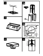
2) ark the centre of the cooking appliance onto the ceiling with a plumb line.  raw the horizontal axes

running parallel to the stove top onto the ceiling as illustrated 

Fig. 1

.

3) Place the drill gauge centred on the axes aligning the axes  on the drill gauge centrally over these axes

as illustrated 

Fig. 2b

.

4) Remove the self-tapping screws, which  x the chimney 

item 7

 to the metal frame bracket as illustrated

in 

Fig. 2a 

and then remove both sides of the upper chimney stacks.

ITTIN  THE CANO   RACKET

5) ark the positions on the ceiling for :      - The cut-out for the ducting    150 mm in the extraction mode

and   200 mm in the remote mode when ducting runs through the ceiling.

- The mains supply cords.

                                                - The 4  xing holes for   10 mm nuts and bolts.

rill the different holes with the appropriate masonry bit.  hen  xing the cooker hood to a plasterboard 

ceiling ensure it is reinforced as illustrated in 

Fig. 3

 and attach using four  10mm nuts and bolts  ensuring 

the bolts as sleeved between the plasterboard and the  oist supports to prevent the ceiling being damaged 

when the bolts are tightened up.

If the ceiling is concrete, use eight   10 mm steel rawl bolts. Plastic rawl plugs must not be used.

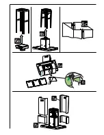
6) Remove the de ector 

Fig. 4

.

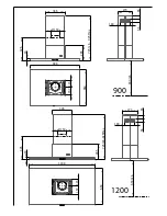
) The height of the cooker hood can be ad usted in 50 mm stages. 650 mm when  tting above an electric

hotplate and  00 mm when  tting above a gas hotplate. Select the height required using the measure

-

ments illustrated in 

Fig. 5


& 6

 and  x the metal diffuser to the frame of the chimney brackets using the 

height 5 x 10T hexagonal headed screws. A drawing on the drill gauge de nes the positioning for the 

controls.

A


) Check the vertical of the chimney.

UCTIN

The hood is more effective when used in the extraction mode (ducted to the outside).  hen the cooker 

hood is ducted to the outside, charcoal  lters are not required.

The ducting used must be 150 mm (6 INS), rigid circular pipe and must be manufactured from  re retard-

ant material, produced to BS.4 6 or  IN 4102-B1.  herever possible utilise rigid circular pipe which has 

a smooth interior, rather than the expanding concertina type ducting.

aximum length of ducting run:  

-   4 metres with 1 x  0  bend.

-   3 metres with 2 x  0  bends. 

-   2 metres with 3 x  0  bends.

The above assumes our 150 mm (6 INS) ducting is being installed. Please note ducting components and 

ducting kits are optional accessories and have to be ordered, they are not automatically supplied with the 

chimney hood.

Summary of Contents for atrium 3 centrale

Page 1: ...Atrium 3 Centrale Mode d emploi et installation Hotte de Cuisine Instructions for use and installation Cooker Hood...

Page 2: ...POSE DE L APPAREIL FONCTIONNEMENT CONSEILS D UTILISATIONS ENTRETIEN GARANTIE ET SERVICE APR S VENTE REMARQUES GB CONTENTS ELECTRICAL WIRING INSTALLATION ADVICE FITTING THE APPLIANCE OPERATION USEFUL H...

Page 3: ...n aucun cas tre raccord e un conduit de ventilation m canique contr l e V C Lorsqu on vacue l air vici dans un conduit d vacuation veiller ce que celui ci ne soit pas d exploit v hiculer des gaz ou fu...

Page 4: ...ettre le clapet anti retour C sur la sortie de l appareil Rep 6 et raccorder le tuyau exible l vacuation ext rieure et la sortie de l appareil Fixer l ensemble l aide de colliers ou de ruban adh sif...

Page 5: ...uyer sur la touche usqu aux clignotements des 5 leds Un clignotement des 5 leds indiquera l enregistrement de la mise en vacuation ext rieure b Fonctions de base Eclairage ise en marche en appuyant su...

Page 6: ...ur et clairage teints appuyer sur la touche 1 clairage usqu au clignotement de la led 1 Deux clignotements de la led 1 indiquent que la t l commande est activ e Un clignotement de la led 1 indique que...

Page 7: ...tion reconnu par le fabricant car des outils sp ciaux sont n cessaires brancher compl tement l appareil Exigez tou ours l utilisation de pi ces de rechange d origine La non observation de cette prescr...

Page 8: ...humidit et liminer les odeurs de cuisine Utilisez la vitesse intensive lorsque cela est strictement n cessaire Augmentez la vitesse de la hotte seulement lorsque la quantit de vapeur le requiert Veill...

Page 9: ...ed ensure that there is an adequate supply of fresh air to the room Ensure the kitchen is tted with an airbrick which should have a cross sectional measurement equivalent to the diameter of the ductin...

Page 10: ...different holes with the appropriate masonry bit hen xing the cooker hood to a plasterboard ceiling ensure it is reinforced as illustrated in Fig 3 and attach using four 10mm nuts and bolts ensuring t...

Page 11: ...hesive tape Fig 6c c ake the electrical connection as described in the section titled ELECTRICAL d Each top and lower chimney stack consists of two sections Place the top chimney with the slops fac in...

Page 12: ...nd proceed as follows Press the LE button for 3 to 4 seconds and the LE lights 1 2 3 4 and 5 will ash to con rm the programme has been reset to zero B I After 400 hours use LE will indicate that you m...

Page 13: ...a month or more frequently if the hood is used for more than 3 hours per day T Remove the metal grease lters one at a time by releasing the catches on the lters the lters can now be removed The metal...

Page 14: ...r the terms of this guarantee REMARKS This appliance complies with European regulations on low voltages irective 2006 5 CE on electrical safety and with the following European regulations irective 200...

Page 15: ...XXXX GB DE IT G E B NL FR Mode d emploi et d installation Instructions for use and installation Bedienungsanleitung und einrichtung XXX XXXX XXX XXX XXXX XXX XXX XXXX XXX Istruzioni per l uso e l ins...

Page 16: ...150 346 46 725 min 925 Max 285 273 180 56 65 898 740 598 660 116 157 426 35 650 min 900 Inox Verre...

Page 17: ...346 285 180 273 56 65 116 157 725 min 925 Max 898 660 740 1198 35 150 46 650 min 6 2 4 1200 Inox Verre...

Page 18: ...40 898 660 346 285 180 273 56 65 116 157 725 min 925 Max 150 650 min 6 2 4 346 40 285 725min 925Max 273 180 65 56 660 1198 150 116 157 650 min 426 900 1200...

Page 19: ...BLEU CLAIR HELL BLAU P PINK ROSE ROSA V PURPLE MAUVE MALVER FARBIG R RED ROUGE ROT W WHITE BLANC WEISS W P WHITE PINK BLANC ROSE WEISS ROSA Y YELLOW JAUNE GELB 100 W 01 01 2015 Atrium 3 centrale 900...

Page 20: ...nnection Unit to BS 1363 Part 4 fitted with a 3 Amp fuse is a recommendedmains supply connectionaccessoryto ensure compliance with the Safety Requirements applicable to fixed wiring instructions The w...

Page 21: ...1 2a 3 7 2b 4 5 50 50 50 50 50 210 220 12 Pour tuyau 150mm For pipe 150mm F r Rohr 150mm Per fori 150mm Para conducto 150mm Voor buis 150mm 160 89 131 40 Alimentation 80 85...

Page 22: ...6c 6b 6a 6d A 6 7a 7b...

Page 23: ...8 9 C 6 11 10...

Page 24: ...d Luci Led Luz Led Verlichting 4 x 1 1 W press or press Il est n cessaire de d poser le support clairage sur certain produit pour acc der au dos du spot It is necessary to remove the light holder on c...

Page 25: ...Plaque Signal tique de la hotte Rating plate of the cookerhood Typenschild im Inneren der Dunstesse Etichetta all interno della cappa Etiqueta de la campana Typeplaatje van de afzuigkap...

Page 26: ...A S 25 Rue des Rosiers Sainte C cile B P 60056 50800 VILLEDIEU LES PO LES France T l 02 33 91 26 50 Fax 02 33 51 54 79 e mail com france roblin fr For outside France Tel 33 0 2 33 91 26 57 Fax 33 0 2...

Reviews: