NOTE:
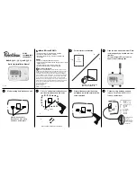
For 9901i single stage heat
pump applications, place a jumper
between the E/W1 and Y1 terminals.
7
Connect wiring between unit and
furnace. For Model 9915i
(2H/2C furnace applications).
8
Replace cover on thermostat.
To replace cover, line up top and
bottom edges and push straight in.
DO NOT pivot on upper case clips.
Turn on power to unit and proceed
with programming per instructions on
the display or in the user’s manual.
12
Connect wiring between unit and
heat pump. For Model 9920i (2H/2C
heat pump applications).
9
To set your name and phone
number into the thermostat press
MENU, select INSTALLER
SETTINGS, and CONTACT
INFORMATION. The screen at the
bottom left should appear.
To enter your name press EDIT.
Use the UP or DOWN button to
scroll through the characters.
(DOWN gets you to the letters
faster.) After each letter press NEXT.
When you are done entering your
name, press ACCEPT.
Connect wiring between the
thermostat and the indoor sensor
(9020i) and the outdoor sensor
(9025i), if used. Use twisted pair
wiring (22AWG minimum) with a
maximum length of 300 feet
(or 100m).
Now enter your phone number.
Use the UP and DOWN arrow to
select the first number. Press NEXT.
When you have completed entering
your phone number, press ACCEPT.
The screen will return to the
INSTALLER SETTINGS. Finish
setting the thermostat for the
application.
Y1
R
C
E/W1
A1 O B G
Thermostat
C - 24VAC Common
R - 24VAC
Y1
- 1st stage cooling
E/W1 - 1st stage heating
W2 - 2nd stage heating
Y2
- 2nd stage cooling
L - Not used
O
- Not used
B - Not used
G
- Fan
A1 -
Aux
contact
A2 -
Aux
contact
TERMINAL DESIGNATIONS
W2
A2
Y2
C
R
Y1
W1
W2
Y2
G
B
L
O
9915
i
Equipment Wiring
Terminals
Please refer to
furnace installation
manual for proper
terminations
Y1
R
C
E/W1
A1 O B G
Thermostat
C - 24VAC Common
R - 24VAC
Y1
- 1st stage heating/cooling
E/W1 - Emergency heat strip
W2 - 2nd stage heating
Y2
- 2nd stage cooling
L
- System fault indicator
O
- Cool active reversing valve
B
- Heat active reversing valve
G - Fan
A1 -
Aux
contact
A2 -
Aux
contact
TERMINAL DESIGNATIONS
W2
A2
Y2
C
R
Y1
E
W2
Y2
G
L
B
L
O
9920
i
Equipment Wiring
Terminals
Please refer to heat
pump installation
manual for proper
terminations
If terminal E is not supplied,
add jumper across E/W1 and
W2 on the thermostat.
Set Your Name
Set Your Phone Number
Y1
R
C
E/W1
A1 O B G
Thermostat
C - 24VAC Common
R - 24VAC
Y1
- 1st stage cooling
E/W1 - 1st stage heating
O
- Cool active reversing valve
B
- Heat active reversing valve
G - Fan
A1 -
Aux
contact
A2 -
Aux
contact
W2 - Not used
Y2
- Not used
L
- Not used
TERMINAL DESIGNATIONS
C
R
Y1
G
B
O
9901
i
W2
A2
Y2
L
Jumper
Equipment Wiring
Terminals
Please refer to heat
pump installation
manual for proper
terminations
CONTACT INFORMATION
BACK
EDIT
ACCEPT
NEXT
CONTACT INFORMATION
AIR EXPERTS
CONTACT INFORMATION
AIR EXPERTS
ACCEPT
NEXT
1
ACCEPT
NEXT
CONTACT INFORMATION
AIR EXPERTS
1-800-445-8299
13
14
111-326C
Controls Americas
515 South Promenade Avenue
Corona CA 92879-1736
United States of America
Made in Mexico
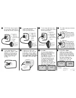
The auxiliary contact relay can be used
in two ways.
a)
Dry Contacts
The A1 and A2 contacts
are factory set as dry con-
tact points. Connect them
to the damper or economizer
as with any set of dry con-
tact terminals.
b)
24V Contacts
Place a jumper between R
and A2. When the relay is
energized, there will be 24V
at A1. To provide 24V power
to the economizer or damper,
wire the unit to the A1 and C
terminals on the thermostat.
Note:
1 amp max load on relay.
10
11
Patents Pending
www.about-i-series.com
Y1
R
C
E/
W1
A
1
O
B
G
Thermostat
9901
i
W2
A
2
Y2
L
To Economizer / Damper
Y1
R
C
E/W1
A1 O B G
Thermostat
9901
i
W2
A2
Y2
L
To Economizer / Damper
Jumper


