

USER CONTROLS (CONT)
OUTDOOR (ODT) BUTTON
If your thermostat has been installed with an electronic outdoor
remote sensor (Uni-Line Part #529), you may view the outdoor
temperature simply by pressing the OUTDOOR button. Upon
releasing the button, the thermostat will once again display the
indoor temperature. If the option is not connected, the thermostat
will display
✜
---.
DAY/NIGHT BUTTON
✥✠
When the thermostat is initially installed, the display will show the
✥
symbol for your day temperature. By pressing the DAY/NIGHT
button you may select an alternate or night temperature
✠
(the
thermostat will remember this setpoint). Simply press the
DAY/NIGHT button to alternate between temperature settings.
CELSIUS / FAHRENHEIT
Simultaneously press
✟
and
✞
to switch between Celsius (C) and
Fahrenheit (F) temperature display.
REMOTE SENSOR (OPTION)
RS1 – RS2 – RS+V
The thermostat is designed to accept the electronic remote sen-
sor (Uni-Line Part #528) which will allow you to locate your ther-
mostat in an area away from view. Indoor and outdoor sensors
are available separately.
CLOCK TERMINALS (OPTION) CLK1 – CLK2
Your thermostat is equipped with a dry contact closure input. By
connecting to any relay-based controller or clock timer (DSP-AT
or equivalent), the thermostat can be alternated between the
DAY/NIGHT (setback) temperature setpoints automatically.
Upon initial power up of the thermostat or after a power failure,
the thermostat will check the clock terminals and apply the DAY
(open contact) or NIGHT (closed contact) temperature setpoints
accordingly.
TEMPERATURE ACCURACY
Full temperature accuracy will only be realized after the thermo-
stat has been installed and powered for at least one (1) hour.
POWER FAILURES
Your thermostat employs the latest in solid state electronic
technology.
One of the unique features of your thermostat is that there is no
battery required to maintain your selected setpoints in the event
of a power loss as the memory is unaffected by power failures of
any duration.
When power is restored, the thermostat will continue operating as
if the power had never been off.
INSTALLATION INSTRUCTIONS
LOCATION
To ensure proper operation, the thermostat should be mounted on
an inside wall in a frequently occupied area of the building. In
addition, its position must be at least 18" (46cm) from any outside
wall, and approximately 5' (1.5m) above the floor in a location
with freely circulating air of an average temperature. You should
avoid the following locations:
– behind doors or in corners where freely circulating air is
unavailable;
– where direct sunlight or radiant heat from appliances might
affect control operation;
– on an outside wall;
– adjacent to, or in line with, conditioned air discharge grilles,
stairwells, or outside doors;
– where its operation may be affected by steam or water pipes or
warm air stacks in an adjacent partition space, or by an area
behind the thermostat which is not climate controlled;
– where its operation will be affected by the supply air of an adja-
cent climate control HVAC device; and
– near sources of electrical interference such as arcing relay
contacts.
REMOVING THE THERMOSTAT FROM THE SUBBASE
1. Insert a flat blade screwdriver or a coin 1/8" into the
slot located in the bottom center of the thermostat
case and twist 1/4 turn. When you feel or hear a “click,”
grasp the case from the bottom two corners and separate from
the subbase. Some models require more force than others
when separating due to the number of terminals used.
2. Swing the thermostat out from the bottom.
3. Lift the thermostat up and off the subbase.
4. Place the rectangular opening in the subbase over the equip-
ment control wires protruding from the wall and, using the sub-
base as a template, mark the location of the two mounting
holes (exact vertical mounting is necessary only for appear-
ance).
5. Use the supplied anchors and screws for mounting on drywall
or plaster; drill two 3/16" (5mm) diameter holes at the marked
locations; use a hammer to tap the nylon anchors in flush to
the wall surface and fasten subbase using the supplied screws.
(Do not overtighten!)
6. Connect the wires from your system to the thermostat termi-
nals. Carefully dress the wires so that any excess is pushed
back into the wall cavity or junction box. Ensure that the wires
are flush to the plastic subbase. The access hole should be
sealed or stuffed to prevent drafts from the wall affecting the
thermostat.
7. Before the thermostat is reinstalled on the subbase, install the
optional clock/timer, indoor remote sensor and outdoor remote
sensor, if used. Refer to the installation instructions supplied
with each option. Also check the position of the DIP switches
on the back of the thermostat.
CAUTION
THIS DEVICE SHOULD BE INSTALLED BY A
QUALIFIED TECHNICIAN WITH DUE REGARD
FOR SAFETY, AS IMPROPER INSTALLATION
COULD RESULT IN A HAZARDOUS CONDITION
INSTALLATION INSTRUCTIONS (CONT)
REPLACING THE THERMO-
STAT ON SUBBASE
1. Position the thermostat on the
hinged tabs at the top of the
subbase.
2. Gently swing the thermostat
down and press on the bottom
center until it snaps into place.
THERMOSTAT COVER LOCK
You may lock the cover down to
prevent unauthorized access to
the thermostat by adding the
plastic lock (included in the instal-
lation bag). Insert the plastic lock
piece into the bottom of the
mounted base. The ends of the
lock piece fit snugly under the
lock pins extending from the bot-
tom of the mounted base. The
tab in the middle of the lock piece
extends down from the base.
To release the locking mecha-
nism, press the lock piece up and
into the base while gently prying
open.
THERMISTOR MOUNTING INSTRUCTIONS
When placing the front cover on the thermostat ensure the
thermistor is not bent or misaligned.
Ensure that the thermistor does not touch the thermostat case.
The thermistor should be placed horizontal to the wall. Ensure the
thermistor is not pushed upward into the case.
The thermistor should be aligned so it is visible between the ribs
on the bottom of the subbase.
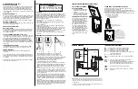
Outside rear view with backplate closed
WIRING DIAGRAM
Note: If the 24V(c) is not available from the equipment, the shunt may be
removed and a separate 24V transformer must then be used to power the
thermostat. To remove jumper (labeled JP1) from the printed circuit board,
pull straight out.
This thermostat may be used with 24 Volt DC. The negative side of the DC
supply must be wired to the 24V (c) terminal.
TERMINAL DESIGNATIONS
W2 .............Energizes on a call for 2nd stage heating
Y2 ..............Energizes on a call for 2nd stage cooling
W1 .............Energizes on a call for 1st stage heating
Y1 ..............Energizes on a call for 1st stage cooling
G ................Fan operates with a call for heating or cooling or by
pressing the FAN button.
R ................Power from equipment
24V ............24 VAC hot and common to power the thermostat
24V(c)
RS2............Use to connect up to 6 (SL-IDS) indoor and/or 1
RS1
(SL-ODT) outdoor remote sensor/s.
RS+V
When connected the thermostat will automatically use
the SL-IDS temperature sensor and not its own.
Refer to the instructions included with the sensor.
LED1..........Free lights for status or function indication
LED2
CLK1 .........Use with dry contact relay or DSP-AT for alternate
CLK2
setpoints
(for Release 3)