background image

Guarantee

This instrument is guaranteed for twelve months from the date of delivery to the original owner against failure due to faulty workmanship or component
breakdown, subject to the procedure stated below. Should any component or part fail during this guarantee period it will be repaired or replaced free of charge.

The guarantee does not cover:

1. Damage resulting from incorrect use.

2. Consequential damage.

3. Receivers with removed or defaced serial numbers.

N.B. Damaged or broken telescopic aerials will not be replaced under guarantee.

Procedure:

Any claim under this guarantee should be made through the dealer from whom the instrument was purchased. It is likely that your Roberts' dealer will
be able to attend to any defect quickly and efficiently, but should it be necessary the dealer will return the instrument to the company’s service department
for attention. In the event that it is not possible to return the instrument to the Roberts' dealer from whom it was purchased, please contact Roberts Radio
Technical Services department at the address shown below before taking further action.

These statements do not affect the statutory rights of a consumer.

ROBERTS RADIO TECHNICAL SERVICES DEPARTMENT

97-99 Worton Road

Isleworth Middlesex

TW7 6EG

Technical Helpline:- 020 8758 0338 

(Mon-Fri)

Issue 1

R9906 Instruction Book.pm6

24/10/99, 14:22

24

Summary of Contents for R9906

Page 1: ...re use P L L D ig ita l 3 B a n d R e c e iv e r R 9 9 0 6 7 9 8 A F R T M a in s P T Y T r a ffic T im e S n o o z e A la rm T u n in g M e m o 1 2 3 4 5 W e e k e n d C a n c e l R D S F M 8 7 5 1 0 8 M H z M W 5 2 0 1 7 1 0 k H z L W 1 4 4 2 9 0 M H z 6 1 0 D is p la y 24 10 99 14 22 ...

Page 2: ...8 19 Display backlight 20 Demonstration mode 20 Lock switch 20 Headphones 21 Troubleshooting 21 General 21 Specifications 22 Circuit features 22 Important Information please read before use To assist the auto setup of your radio it is recommended before connecting your radio to a power supply batteries or mains to fully extend the telescopic aerial and place your radio in a position where radio re...

Page 3: ...presets hen MW or o will show ation of the me setting carryClock o another lock is set stops one of the using the r button ete and is your area mobutton ations can ons D is p la y 7 9 8 1 2 3 4 5 6 1 0 ON 2 24 10 99 14 22 ...

Page 4: ... e k e n d C a n c e l R D S F M 8 7 5 1 0 8 M H z M W 5 2 0 1 7 1 0 k H z L W 1 4 4 2 9 0 M H z 6 1 0 D is p la y 2 4 13 3 5 6 7 9 10 11 12 14 15 16 9 Sleep button 10 Alarm mode button 11 Display button 12 Powerbutton 13 Weekend cancel button 14 Memory buttons 15 Preset buttons 16 Alternate frequency button 1 8 17 17 Radio text button 24 10 99 14 22 ...

Page 5: ...4 Right side 21 olume control eadphonesocket Mains socket elescopicaerial Wavebandswitch ey lock switch on underside 22 F M M W L W 23 24 10 99 14 22 ...

Page 6: ...cator 8 Sleep time indicator 9 Programme type indicator 10 Radio alarm indicator 11 Buzzer alarm indicator 12 Wavebandindicator 13 Frequency time and text display area 6 3 4 5 7 9 8 10 11 24 10 99 14 22 ...

Page 7: ...ear of your he Mains ted to the O N ushing the ces in the s into the ensure all inside the k memory signs that sed for any 14 C size sed on the asional or 6 24 10 99 14 22 ...

Page 8: ...T u n in g n receiving rmation is al strength mbol equency in stop when sufficient al display al display The dio station other radio he radio is tting clock D is p la y F M M W L W T im e 24 10 99 14 22 ...

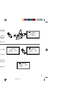
Page 9: ...mbol the or shown as D is p la y T im e T u n in g k using the e D is p la y S n o o z e T u n in g 8 24 10 99 14 22 ...

Page 10: ...press and he display switch off ned off for ndrelease e display A la rm D is p la y D is p la y A la rm using the e ck time will A la rm T u n in g D is p la y D is p la y 24 10 99 14 22 ...

Page 11: ...sing ing the 90 S n o o z e d isreached choffafter red press D is p la y 10 o the level press and he display switch off ned off for nd release he display A la rm D is p la y D is p la y A la rm 24 10 99 14 22 ...

Page 12: ...roceed as on until the sound on ction The W e e k e n d C a n c e l W e e k e n d C a n c e l 24 10 99 14 22 ...

Page 13: ...scopic n s until the he button imeitfinds rol to the re Search ning or F M M W L W T u n in g waveband elescopic n hange the MW9kHz evel F M M W L W T u n in g D is p la y D is p la y D is p la y 12 24 10 99 14 22 ...

Page 14: ...avebands methods will flash in ons under btained by umber will Memory is F M M W L W M e m o T u n in g M e m o D is p la y 7 9 8 1 2 3 4 5 6 1 0 D is p la y 24 10 99 14 22 ...

Page 15: ... D ig ita l3 B a n d R e c e iv e r R 9 9 0 6 7 9 8 A F R T M a in s P T Y T ra ffic T im e S n o o z e A la rm T u n in g M e m o 1 2 3 4 5 W e e k e n d C a nc e l R D S F M 8 7 5 1 0 8 M H z M W 5 2 0 1 7 1 0 k H z L W 1 4 4 2 9 0 M H z 6 1 0 D is p la y 14 24 10 99 14 22 ...

Page 16: ... for the station being received You can switch to those frequencies directly if desired Programme Type PTY This is an identification number transmitted with each programme to specify the type of the programme being broadcast e g NEWS ROCK CLASSIC etc The PTY number can be used so that search tuning responds only to the selected programme type Radio Text RT Radio Text is a text message of up to 64 ...

Page 17: ...ystem o seconds symbol will frequency k for RDS stationyou o a station alternate nformation on you are y and the ation name F M M W L W D is p la y D is p la y A F 16 24 10 99 14 22 ...

Page 18: ...s in length ight to left o a station ear in the rom left to wn the RT T R T WS ROCK o a station s the PTY display will nds P T Y 24 10 99 14 22 ...

Page 19: ...P T Y ndrelease own in the e When a the station pe search either the o an RDS nformation ymbol will nformation he display T ra ffic 18 T u n in g 24 10 99 14 22 ...

Page 20: ...n the EON ally tune to traffic an previously Radio 4 it sting traffic cal station station h you are t on a local se circum back to the symbol T ra ffic 24 10 99 14 22 ...

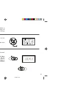
Page 21: ...henever a ation and hilst these to prevent ThePower accidental any button display to to the left hen active lay enters D is p la y 20 24 10 99 14 22 ...

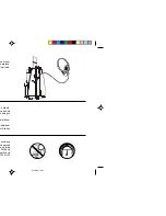
Page 22: ...o not leave n a parked he outside e FM band uality and MW or LW nd of your earpiece ernal loud V o lu m e m carpets eceivebad ponding to nstall them individual st Station 24 10 99 14 22 ...

Page 23: ...0 mW into 4ohms Headphonesocket 3 5mm dia Aerial System FM Telescopicaerial MW Built in Ferrite aerial LW Built in Ferrite aerial ROBERTSRADIOLIMITED PO BOX 130 MEXBOROUGH SOUTH YORKSHIRE S64 8YT s the right to amend the specification without notice 22 24 10 99 14 22 ...

Page 24: ...rantee ealer from whom the instrument was purchased It is likely that your Roberts dealer will it be necessary the dealer will return the instrument to the company s service department ument to the Roberts dealer from whom it was purchased please contact Roberts Radio fore taking further action o not affect the statutory rights of a consumer CHNICAL SERVICES DEPARTMENT 97 99 Worton Road IsleworthM...

Reviews: