SECTION 1: H
EATER
S
AFETY
3 of 51
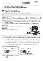
Fi
g
ure 2: UHA[X][S]200 - 250 Label Placement
*For separated comb
u
stion
u
nits only.
Description
Part Number
Logo Label
91040030
C
u
t Hazard Label
91010430
Vent Length Label
91039505
Vent to O
u
tdoors Label
91010427
Warning Label
91010429
Rating Plate Label
91010419
Installation Label
91010431
Instr
u
ction Location Label
91010433
Lighting Instr
u
ction Label
91010425
Venting Arrangement Label*
91010426
Proposition 65 Label
91070015