


SS550 Métallique 30” High Cabinet
2. Selecting Location • Surface or Recess
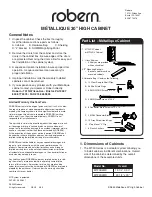
Carefully select the cabinet location, keeping in mind
the following:
A. Clearance from the faucet must be determined.
B. When recessing be sure clearance is provided
above the rough opening for the top of the door.
C. Depth of recess must be 4”.
SURFACE
INSTALLATION
1" CLEARANCE
1" CLEARANCE
RECESSED
INSTALLATION
SINK AND
FAUCET
SINK AND
FAUCET
3. Surface Mount Cabinet (See page 3 for Recessed Instructions.)
1. Each cabinet is shipped with an aluminum “Z”
mounting bar.
2. It is strongly recommended that a support similar to
that used for a wall mounted sink be framed in the
wall during construction as shown in figure B.
3. Drill a 7/32” hole through the indent line on the
mounting bracket (See figure B.) at the stud or
furring strip location. Use the plastic anchors
supplied if no furring strip has been installed,
making sure each cabinet is supported by at
least three anchors.
Follow the Poly-set Anchor instructions on this
page for anchors supplied. Be sure mounting
bar is level.
4. Three “Z” clips are supplied for the top of each
cabinet. These clips slide into the screw channel
on the top of the cabinet. Holes for the clips can be
pre-drilled per dimensions shown in figure C.
5. The MTSK30 side kit is used to finish the sides of
the surface mount installation.
1. Attach bracket to cabinet using
#10 X 1/2” Screws. Be sure you do not over
tighten. (See figure D.)
2. Cap screw heads with covers provided.
LOCATE BRACKET
TO CLEAR SINK
FAUCETS BY AT LEAST
ONE INCH.
MOUNTING BRACKET
#10 X 2"
SMS/WOOD SCREW
1 X 3 FURRING STRIP
BEHIND WALLBOARD
OR TILE. LOCATED
AT CENTER OF BOTTOM
EDGE OF CABINET.
Poly-set Anchor Instructions for Hollow Walls
1. Drill 9/32” hole and insert anchor
until flange is flush.
2. Insert #10 X 2” SMS/wood screw
through bracket and anchor.
Continue to turn screw to fully
expand the anchor according to
the chart below.
Total Wall
Thickness
1/2”
5/8”
3/4”
Turns after screw head
is against bracket
8-9 Turns
6-7 Turns
4-5 Turns
W
A
LL
1.325
29 1/8"
30"
Fig. B
Fig. C
Fig. D
Fig. A
CABINET
#10 X 1/2" screws
MTSK30
Side Kit
Mirror


