5
6
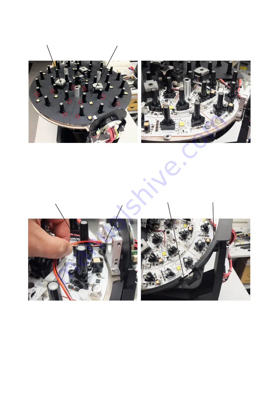
4. Remove PCB covers (6) and (7) by unscrewing 10 fastening screws (screws in red circles on the picture
below)..
7
5. Pass the connecting cable (8) through the pivot (9).
6. Screw the new head cover (11) with the aperture (10) for connector on the head.
9
8
10
11


