background image

10

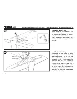
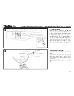
7. Installing the elevator linkage

Glue the horn in the elevator permanently using 
Ropoxi 5-minute epoxy.
Slip the elevator pushrod through the opening in 
the fuselage, and install it as shown.
Prepare the elevator servo as shown in the il-
lustration, and set it to centre (neutral) from the 
transmitter.

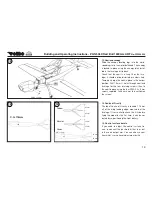
8. Installing the rudder linkage

Thread the braided cable through the opening 
in the fuselage, as shown in the illustration. Slip 
a brass crimp-sleeve onto the end of the cable, 
followed by the ring-screw. Now form a loop in 
the cable, and thread it through the brass slee-
ve a second time. Firmly crimp (squeeze) the 
sleeve to secure the cable, using crimp pliers 
or an electrical connector crimping tool. Screw 
the ball-link onto the ring-screw. Glue the rudder 
horn in place using Ropoxi 5-minute epoxy. Con-
nect the prepared cable to the horn as shown. 
Repeat this procedure with the second cable on 
the other side of the rudder.

7

8

Pm 2 x 10 mm

Building and Operating Instructions - ZLIN 50LX Red Bull 1600mm ARF 

No. FW004004

Control 

         surface horn

M2 mm

Washer

2 I.D. x 6 mm I.D.

Ball-link

Pushrod, 2 x 770 mm

PM 2 x 10 mm

Brass sleeve

Ring-screw M 2.2 mm

Braided cable, 840 mm

Ball-link

M2 mm

Washer

2 I.D. x 6 mm I.D.

Control surface 

horn

Summary of Contents for ZLIN 50LX RED BULL 1600MM ARF

Page 1: ...FW004004 ZLIN 50 LX Red Bull 1600mm ARF Building and Operating Instructions ...

Page 2: ...ent parts list 15 Dear fellow modeller Congratulations on purchasing the robbe Flite work ZLIN 50LX Red Bull 1600 mm this ver sion is produced by one of the world s finest model manufacturers We also wish to thank you for the trust you have shown in us by bu ying the model We hope you have many en joyable hours flying the robbe Flitework ZLIN 50LX Red Bull 1600 mm CAUTION Radio controlled model ai...

Page 3: ...s may become hot when operating It is essential to avoid touching such parts Do not stand close to the hazard area around rotating parts when an electric motor is connected to the flight battery You must also take care to keep all other objects away from moving or rotating parts Observe the instructions provided by the battery manufacturer Overcharged or incorrectly charged batteries may explode T...

Page 4: ...craft you will need to ex tend the cover of your existing policy or take out specific insurance Check your insurance policy and take out new cover where necessary Liability Exclusion robbe Modellsport is unable to ensure that you observe the assembly and operating instruc tions or the conditions and methods used for installing operating and maintaining the model components For this reason we accep...

Page 5: ...o introduce technical modifications at any time These instructions are intended to aid and guide you when com pleting the model The illustrations and notes do not represent legal obligations We will not countenance legal actions derived from them Essential tools and adhesives Cross point screwdriver Twist drills 1 5 mm 2 mm and 4 mm Adhesive tape Ropoxi 5 minute epoxy Low viscosity cyano acrylate ...

Page 6: ... PEAK C8 EQ BID 12 V 230 V 180 W 1 x 8124 CT4 gold charge lead 4 mm 1 x 4059 Specification Wingspan approx 1612 mm Length approx 1403 mm Scale 1 5 5 Total surface approx 46 6 dm2 Wing loading approx 65 g dm2 All up weight approx 3050 g 6 Set contents Fuselage wings tail panels and control surfaces factory assembled from laser cut wooden components covered in printed high gloss film Ready made GRP ...

Page 7: ...t them working loose Prepare the aileron servo output arm as shown and install the servo as shown in the illustration Now set the servo to centre neutral from the transmitter and connect the pushrod to the servo Connect the other end to the aileron horn Adjust the linkage so that the aileron is not deflected up or down at the neutral point Repeat the procedure with the second wing panel 1 2 Buildi...

Page 8: ...ng the tailplane Use a sharp balsa knife to cut away the covering film over the tailplane slot in the fin Remove the film over the joint area of the tailplane The tail plane can now be glued in the fin using Ropoxi 5 minute epoxy Glue the elevator hinges in the tailplane using cyano Take care to set the tailplane exactly at right angles to the fuselage centreline 3 4 Plywood wing joiner 375 x 33 x...

Page 9: ...cyano Install the rudder as shown When the glue has set hard check that the rud der deflects freely to both sides and carry out any adjustments required 6 Installing the tailplane struts The tailplane struts are attached using 1 5 mm aluminium brackets which are screwed to the struts the fuselage and the tailplane 5 6 Building and Operating Instructions ZLIN 50LX Red Bull 1600mm ARF No FW004004 Co...

Page 10: ...a loop in the cable and thread it through the brass slee ve a second time Firmly crimp squeeze the sleeve to secure the cable using crimp pliers or an electrical connector crimping tool Screw the ball link onto the ring screw Glue the rudder horn in place using Ropoxi 5 minute epoxy Con nect the prepared cable to the horn as shown Repeat this procedure with the second cable on the other side of th...

Page 11: ...ightening the clamping screws 10 Installing the undercarriage The undercarriage is installed as shown in the drawing Screw the undercarriage unit to the mounting plate in the fuselage using the three M4 x 16 mm screws supplied Take care not to over tighten the screws Now install the wheels as shown in the illustra tion 9 10 Building and Operating Instructions ZLIN 50LX Red Bull 1600mm ARF No FW004...

Page 12: ...ount and the motor flange 12 Installing the wing Locate the retaining lug in the centre of the wing and insert it in the corresponding slot in the un dercarriage former Fix the wing to the fuselage using the two M4 x 30 screws 4 I D x 12 mm O D washers and the plywood reinforcement see illustration 11 12 4 I D x 10 mm O D M4 x 30 mm 4 I D x 12 mm O D Building and Operating Instructions ZLIN 50LX R...

Page 13: ...ied Take care not to over tighten the screws 14 Centre of Gravity The ideal Centre of Gravity is located 118 mm aft of the wing leading edge measured at the fuselage It is essential to check the C G before flying the model for the first time it can be cor rected by re positioning the flight battery 15 Control surface travels If you need to adjust the control surface tra vels re connect the pushrod...

Page 14: ...with a reasonable rate of climb hands off Check the model s response to control commands You may need to increase or reduce the control surface travels after the first landing The stated control travels are just a guide for the first few flights The exact settings should be selected to suit the individual pilot s flying style Check the model s stalling speed at a safe height Keep the airspeed well...

Page 15: ...ion FW0040041 Cockpit FW004014 Cowl FW004024 Canopy FW004034 Undercarriage complete FW004044 Wing set FW004054 Fuselage set FW004064 Elevators FW004074 Rudder FW004084 Linkage set FW004094 Spinner Building and Operating Instructions ZLIN 50LX Red Bull 1600mm ARF No FW004004 ...

Page 16: ...rsonal liability robbe Modellsport Beteiligungs GmbH Gießen HRB 5793 Managing Director E Dörr Errors and technical modifications reserved Copyright robbe Modellsport 2013 Duplication and copying of the text in whole or in part is only permitted with the prior written approval of robbe Modellsport GmbH amp Co KG 16 Building and Operating Instructions ZLIN 50LX Red Bull 1600mm ARF No FW004004 ...

Reviews: