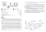
condizioni, se si usa un filtro con una frequenza di taglio eccessiva si rischia che venga emessa
una o più armoniche della frequenza di trasmissione, ciò comunque non danneggia l'amplifica-
tore), se la frequenza di trasmissione è maggiore di quella di taglio interviene il circuito di
protezione dell'amplificatore (accensione del LED rosso
d
) impedendo la commutazione in
trasmissione.
L'interruttore
^
^
^
^
^
permette l'accensione dell'amplificatore lineare.
L'interruttore
\
\
\
\
\
permette l'accensione del preamplificatore d'antenna.
Il preamplificatore d'antenna è indipendente dal funzionamento dell'amplificatore lineare.
Per un ottimo funzionamento, con un basso livello di intermodulazione da parte dei forti segnali
presenti in HF, è costituito da un circuito accordato sintonizzabile tramite il comando
[
. Per l'uso
è necessario avere un segnale in antenna, anche appena udibile, sulla frequenza d'uso o su una
frequenza vicina (con preamplificatore spento), accendere il preamplificatore e sintonizzarlo con
il comando
[
fino al punto di massima intellegibilità del segnale.
Quando l'amplificatore è in trasmissione l'indicatore
TX
(
b
) si accende e la potenza
d'uscita viene indicata dallo strumento (
e
) .
L'indicatore
Protection
(
d
) si accende (rosso) solo se si è verificata una condizione di
pericolo per l'integrità dell'amplificatore. Le cause possibili sono, come già visto, la selezione
di un filtro per una frequenza inferiore a quella effettiva di utilizzo, oppure ad un eccessivo livello
di onde stazionarie (ROS) in antenna.
Controllare il filtro impostato tramite il commutatore
`
o il livello di ROS in antenna prima di
continuare con l'uso dell'amplificatore.
Per ripristinare l'uso normale dell'amplificatore agire su
^
spegnendolo e riaccendendolo.
Se viene utilizzata la connessione
ALC
(
j
) con il trasmettitore può essere necessario adattarne
il livello. Per questa taratura si procede come segue:
Usare un wattmetro tra trasmettitore e lineare,regolare il livello di potenza del trasmettitore a circa
15W FM su una delle seguenti bande 15-17-20-30 o 40 m, regolare il trimmer
l
tutto in senso
orario, accendere il lineare ed andare in trasmissione, regolare ora il trimmer
l
lentamente in
senso antiorario fino ad avere circa 11 W in ingresso all'amplificatore, eccedere nella potenza
farebbe intervenire l'attenuatore o la protezione.
Usare l'amplificatore solo per collegamenti a lunga distanza evitando di rimanere in
trasmissione per più di 5 minuti consecutivi senza intervalli ragionevoli per permettere il
raffreddamento dei transistors.
Garanzia mesi 24 dalla data dello scontrino o ricevuta
Si ricorda che l'utilizzo degli amplificatori lineari è regolato da leggi specifiche e quindi
se ne consiglia la visione prima dell'utilizzo e comunque la ditta costruttrice declina ogni
responsabilità derivata da un non corretto uso rispetto le norme vigenti.
La non osservanza delle istruzioni sopra scritte annulla ogni forma di garanzia che comunque
non include le parti estetiche ed i transistors finali.
DESCRIPTION
The linear amplifier
BLA 300
is properly studied for raising the power in antenna of
decametric apparatus at low power (such as Yaesu FT 817, Icom IC 703…) keeping high the
attenuation characteristics of unwanted emissions (extraneous and harmonic) to establish
long and very long distance connections.
It operates in all the radio amateur bands from 160 (1,8 MHz) to 10 (29,5 MHz) metres
and in all the operative ways.
It internally has a set of six low-pass filters with cut-off frequency of 3/4, 5/8/15/22/
31 MHz for definitively eliminating harmonic emissions. The filter selection control is manual
(cut-off frequency through commutator
`
).
A thermic sensor stops the amplifier working in case of increased temperature. The
reset is automatic in the normal working range.
A protection circuit for an excess of ROS ( protection state is displayed through the
red colour of the indicator
d
) provides to stop the amplifier if the stationary waves level in
antenna is too high.
The same circuit protects the stage of amplification for a possible wrong statement
of the low-pass filters. Reset is by switching off the amplifier through the switch
^
for few
seconds.
A further circuit protects the amplifier from the damages for an excess of input power.
If this one overcomes the 12-13 W the attenuator is automatically set in at -3Db (displayed by
green led
d
ignition ). If the power goes up to 25 W the amplifier is excluded and the state
of protection is indicated through the red led (
d
) ignition.
Internally it has a fan to dissipate the produced heat. It runs variable-speed to reduce
the noise in reception when his usage is less necessary.
INSTALLATION
After taking away the amplifier from its packing and checking any possible damages
during the transport, connect, with a 90 cm long RG58 patch cord, the two-way radio to SO239
connector, named RTX (
i
)
and the antenna to ANT (
h
) connector, both placed on the back
of the amplifier.
Make sure the network switch (
f
) is on off and connect the supply cable on issue
to the back plug (
g
), cutting it in completely. The other extremity has to be plugged in an
appropriate net drive.
For the correct working of the amplifier, it is advised to use also the connections ALC
(
j
) and PTT (
k
), linking them to the correspondent amplifier connections.
Always put the amplifier so as to reach easily all the controls, leaving some space
around it to permit a good ventilation.
ATTENTION


