background image


15 • 72-2102-07 Beacon 200 Operator’s Manual

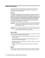
 1. Select the mounting site. When you select the mounting site consider 

the following factors:

Is an AC or DC power source available?

Is there enough room to open the housing door and make wiring 
connections through the conduit hubs at the bottom of the housing?

Are the display screen and status lights visible?

Mounting
Feet , 4X

8.0 M ax

Ø .31 x .50 slot, 4 X

RE SET

Buzzer

.41

3/4 C onduit
Hubs ( 3X)

3/4 C able
Bushings ( 2X)

FA IL

P ILOT

Reset

Switch

7.00

6.45

AL AR M 2

AL AR M 1

4.83

8.5 0

6.0 0

10. 50

10.94

BEACON 20 0

GAS M ON ITOR

 Figure 6.  Beacon 200 Outline and Mounting Dimensions 

Summary of Contents for 72-2102-07

Page 1: ...www rkiinstruments com 72 2102 07 Beacon 200 Operator s Manual Part Number 71 0364 Revision A Released 12 11 17 ...

Page 2: ... calibration and maintenance of the 72 2102 07 Beacon 200 is essential for proper operation and correct readings Please calibrate and maintain this 72 2102 07 Beacon 200 regularly Frequency of calibration depends upon the type of use you have and the sensor types Typical calibration frequencies for most applications are between 3 and 6 months but can be required more often or less often based on y...

Page 3: ...or replacement costs local repair costs transportation costs or contingent expenses incurred without our prior approval THIS WARRANTY IS EXPRESSLY IN LIEU OF ANY AND ALL OTHER WARRANTIES AND REPRESENTATIONS EXPRESSED OR IMPLIED AND ALL OTHER OBLIGATIONS OR LIABILITIES ON THE PART OF RKI INSTRUMENTS INC INCLUDING BUT NOT LIMITED TO THE WARRANTY OF MERCHANTABILITY OR FITNESS FOR A PARTICULAR PURPOSE...

Page 4: ...tion 8 Chapter 3 Installation and Start Up 14 Overview 14 Mounting the Beacon 200 14 Wiring the Beacon 200 17 Starting Up the Beacon 200 23 Chapter 4 Operation 24 Overview 24 Normal Operation 24 Recorder Output Operation 25 Alarm Indications 26 Viewing Resetting Min Max Readings 31 Chapter 5 Channel Control and Setup Program 32 Overview 32 Enable Disable Channel s Menu 33 Configure Channel Setting...

Page 5: ...on 200 Operator s Manual Chapter 6 Maintenance 37 Overview 37 Calibration Program 37 Adjusting Strobe Horn Volume 43 Replacing Components of the Beacon 200 45 Preventive Maintenance 47 Troubleshooting 49 Parts List 52 ...

Page 6: ...on a user defined length of cable The Beacon 200 displays the current gas readings on an LCD display which is visible through the window in the cover front face and provides a 4 20 mA signal which indicates the target gas reading for use by a recording device or programmable controller Three sets of relay contacts two controlled by the gas alarms and one by the fail alarm rated at 115 VAC 10 amps ...

Page 7: ... uses the following conventions for notes cautions and warnings NOTE Describes additional or critical information CAUTION Describes potential damage to equipment WARNING Describes potential danger that can result in injury or death Caution refer to accompanying documentation Vac AC voltage Vdc DC voltage ...

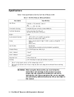
Page 8: ...s polyester with lexan window NEMA 4X Controller Dimensions 21 0 in H x 8 5 in W x 7 00 in D 533 mm H x 216 mm W x 178 mm D Weight 20 lbs Environmental Conditions 20 C to 50 C 4 F to 122 F max ambient Maximum humidity of 80 relative Relays Relay contacts rated for 10A 115 220V resistive or10A 30V resistive SPDT Form C User Controls Reset switch Program buttons ESCAPE UP YES DOWN NO and ENTER Detec...

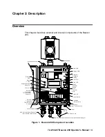
Page 9: ...m inal Stri p Fuses A C Fai l L ED Pilot L ED N O N C C C O M A 2 Controller Term inal S trip Alarm Terminal S tri p Relays Detector Transmitter Term inal S trip Channel 1 Alarm 1 LED Di splay Contrast Adjust Pot Detector Transmitter Term inal S trip Channel 2 Button Repeater Buzzer Fuse DC Mounting Foot 4X Horn Strobe AC P ower Cord Reset Switch Conduit Hub 3X Power Switch N O N C C N O N C C C H...

Page 10: ...housing are for external wiring connections CAUTION Only use the three factory installed conduit hubs on the bottom of the housing for wire entry into the housing Do not drill the housing for any reason CAUTION To avoid electrical interference do not route detector head and power wiring through the same conduit hub Reset Switch The reset switch is on the bottom of the housing It is in front of the...

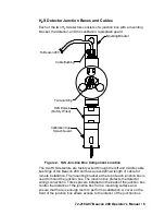
Page 11: ...he mounting bracket at the top of each junction box is used to mount the junction box The junction box protects the detector wiring connections Three spacers installed on the back of the junction box control the distance of the junction box from a mounting surface and ensure that there is enough room to perform a calibration A cover on the front of the junction box allows access to the interior of...

Page 12: ...within the sensor housing by four pins Through a series of chemical and electrical reactions the sensor produces an electrical output that corresponds to the detection range of the detector A pre amplifier located between the sockets and two interconnect wires conditions the sensor s signal before the signal reaches the controller A rubber boot and spacer are installed on the sensor face to ensure...

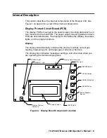
Page 13: ...scribed below The display PCB includes the display the status lights and the program buttons Display The display simultaneously indicates the channel number current gas reading measuring unit and target gas of all active channels The display also indicates messages settings and other data when you are operating the instrument programs J1 UP YES Button ENTER Button DOWN NO Button Display Cable Conn...

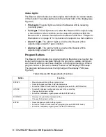
Page 14: ... The Beacon 200 includes four program buttons that allow you to enter the instrument programs navigate through the programs update instrument and channel settings and save changes to the program settings When a program button is pressed a buzzer located on the display PCB beeps The program buttons are near the right edge of the display PCB see Figure 4 Table 2 Beacon 200 Program Button Functions B...

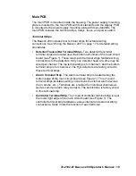
Page 15: ... facilitate wiring connections to the detectors Only one detector head at a time may be wired per channel The top terminal strip is for channel 1 and the bottom terminal strip is for channel 2 The H2S detectors are factory wired to these terminal strips Alarm Terminal Strip The alarm terminal strip is located along the bottom edge of the main circuit board see Figure 1 This 21 point terminal strip...

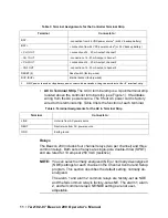
Page 16: ...rm 1 and alarm 2 common relays are factory set as NDE and the fail common relay is factory set as NE The alarm 1 alarm 2 and fail common relays NE NDE settings are not user adjustable Table 3 Terminal Assignments for the Controller Terminal Strip Terminal Connects to BAT connection from 24 VDC power source1 or 24 V backup battery BAT connection from 24 VDC power source1 or 24 V backup battery CH1 ...

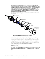
Page 17: ...ondition The common alarm 1 relay is factory wired to the strobe horn and is not available for customer use Fuses There are three fuses that are used in the Beacon 200 Two of them are AC fuses and one of them is a DC fuse AC Fuses The two fuses located directly to the left of the controller terminal strip are the AC fuses They cut off the incoming AC power in the event of a short circuit or other ...

Page 18: ...ee Figure 1 The power switch turns the incoming AC power source on and off at the Beacon 200 When the switch is up the power switch is on NOTE The DC power input has no on off switch and is not affected by the position of this switch Power Supply The power supply is mounted to the power supply mounting plate which is located behind the display PCB The power supply mounting plate is mounted to the ...

Page 19: ...nd start up the monitor WARNING Perform all installation and start up procedures in a fresh air environment known to be free of combustible gas toxic gas and of normal oxygen content The Beacon 200 is not in operation as a gas monitoring system until the start up procedure is complete Mounting the Beacon 200 Perform the following procedure to install the Beacon 200 at the mounting site ...

Page 20: ...the housing door and make wiring connections through the conduit hubs at the bottom of the housing Are the display screen and status lights visible Mounting Feet 4X 8 0 Max Ø 31 x 50 slot 4X RE SET Buzzer 41 3 4 Conduit Hubs 3X 3 4 Cable Bushings 2X FAIL P ILOT Reset Switch 7 00 6 45 AL ARM 2 AL ARM 1 4 83 8 50 6 00 10 50 10 94 BEACON 200 GAS MONITOR Figure 6 Beacon 200 Outline and Mounting Dimens...

Page 21: ...eet to their mounting position as shown in Figure 6 then tighten the screws 5 Insert 1 4 in or 5 16 in screws through the slots in the mounting feet at each corner of the housing to secure the housing to the mounting surface see Figure 6 6 Hang each H2S detector junction box using the mounting bracket Ensure that the detectors are facing down Figure 7 H2S Detector Outline and Mounting Dimensions D...
Page 22: ... Power Supply CH2 OUT RES ET S LEL OXY GEN AMP P RE AMP NO N C C BUZ CH1 OUT RES ET COM A1 CH2 A2 CH2 A1 NO N C C NO N C C NO N C C Channel 2 Channel 1 Black Red S OXY GEN AMP P RE AMP LEL Black Red Buzzer BUZ V V A DJ L AC N AC G A C COM COM GND NEUT LINE COM FAIL COM A2 NO N C C Detector Wiring R W G B V Detector Cable Conduit Hubs N OTU SE D N OT U S ED Detector Cable R W G B NO N C C Reset Swi...

Page 23: ...ible shorting of Beacon 200 components due to wires routed across the PCBs Connecting the AC Power Source NOTE If you are using DC power as the primary power source go to the next section Connecting the DC Power Source The 8 foot AC power cord is routed through the right hand cable bushing on the bottom of the housing and is factory wired to the AC In terminal strip Additional wiring is not necess...

Page 24: ...sion of the detector head signal to the monitor CAUTION When a battery is used as backup power the Beacon 200 trickle charges the battery Do not use a non rechargeable battery as backup power Use RKI backup battery 49 8102RK or an appropriately rated rechargeable lead acid type battery 5 Connect the DC wires to the controller terminal strip as shown in Figure 7 NOTE If a 24 VDC battery is used as ...

Page 25: ... the power source end 2 Open the housing door then place the power switch in the OFF position Locate the alarm terminal strip see Figure 1 3 Guide the wiring of the external alarm device through the cable bushing on the right most conduit hub on the bottom of the Beacon 200 housing The power wiring should already be installed through this cable bushing CAUTION Only use the three factory installed ...

Page 26: ...urn off or unplug all incoming power to the Beacon 200 at the power source end 2 Open the housing door then place the power switch in the OFF position Locate the recorder output terminals on the controller terminal strip see Figure 1 NO NC C NO NC C NO NC C NO NC C NO NC C COM A1 COM A2 COM FAIL CH1 A2 CH2 A1 CH2 A2 Alarm Devices Alarm Device Power Alarm Terminal Strip NO NC C NO NC C CH1 A1 Conta...

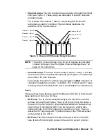
Page 27: ...ION Only use the three factory installed conduit hubs on the bottom of the housing for wire entry into the housing Do not drill the housing for any reason See Routing Wiring Into the Beacon 200 Housing on page 18 for more information 4 Connect the wires from the recording device to the recorder output terminals as shown in Figure 12 CH2 OUT CH1 OUT Recording Device 2 1Kohm Max Impedance Recording ...

Page 28: ... incoming power source AC or DC at the power source end 4 Place the Beacon 200 s power switch in the ON position RKI INSTRUMENTS BEACON 200 appears on the display for a few seconds then WARMING UP appears for each active channel The warm up period will last for one minute NOTE To prevent unwanted alarms during warm up the alarm circuits are not active while the WARMING UP message is displayed 5 Ve...

Page 29: ...ration is defined as follows The start up procedure is complete The Beacon 200 is not indicating an alarm 1 alarm 2 or fail condition The Beacon 200 is not running the Channel Control Setup or Calibration Programs During normal operation the Beacon 200 simultaneously displays the current gas reading unit of measure and target gas for each active channel The PILOT light is on during normal operatio...

Page 30: ... the recorder output will be at 4 mA If the Beacon 200 is being powered by a battery and is in low battery alarm the recorder output for each channel will be 0 mA When a channel is added or a channel type changed the display will indicate NEEDS CALIBRATION for that channel when the Beacon 200 is first turned on and will continue to indicate this until the channel is calibrated In this situation th...

Page 31: ...nt ALARM 1 light is on Gas reading flashes and alternates with ALARM 1 message Strobe horn turns on Pulsing tone Alarm 21 Increasing gas reading at or above the alarm 2 setpoint ALARM 2 light is on Gas reading flashes and alternates with ALARM 2 message Pulsing tone Fail Disconnected or misconnected detector wiring Display reading below 10 of full scale or lower Defective components FAIL light is ...

Page 32: ...ndition as follows The ALARM 1 light turns on The gas reading in alarm 1 condition flashes and alternates with the ALARM 1 message The buzzer sounds a Pulsing tone The common alarm 1 relay energizes and the strobe horn activates The applicable alarm 1 channel relay energizes Responding to an Alarm 1 Condition This section suggests response to an alarm 1 condition 1 Follow your established procedur...

Page 33: ...esponse to an alarm 2 condition 1 Follow your established procedure for a high level H2S condition 2 Alarms are latching After the gas reading falls below the alarm 2 setpoint press the reset switch to reset the alarm circuit Resetting the alarm circuit turns off the ALARM 2 light and de energizes the common and channel alarm 2 relays NOTE To silence the buzzer while in an alarm 2 condition press ...

Page 34: ...This section suggests response to a fail condition 1 Verify that the detector head wiring to the Beacon 200 is correctly and securely connected 2 Verify that the detector head s detector is correctly and securely connected 3 See the troubleshooting guide in the detector head instruction manual Low Battery Condition This section describes the audible and visual indications for a low battery conditi...

Page 35: ...ary DC power source disconnect primary DC power at the Beacon 200 then connect a 24 VDC backup battery 2 Determine and correct the cause of primary DC power loss When the DC power source rises above 22 0 volts the Beacon 200 begins the warm up process If DC power is the backup power source 1 Replace or recharge the 24 VDC backup battery to resume backup power capability 2 Determine and correct the...

Page 36: ...he maximum is on the right side of the display for each channel 3 Press and release the Reset switch button to exit the min max screen The display will indicate To RESET Min MAX values Press and HOLD RESET Button for 10 seconds and then return to normal operation To return to normal operation without resetting the minimum and maximum readings do not press the Reset switch button and allow the unit...

Page 37: ... a program time out the active channels enter a warm up period just as they do when the unit is first turned on If you are installing a new system the channels have been setup at the factory for the ordered detector heads Use the Channel Control Setup Program only if you want to disable or enable a channel delete a channel or change channel settings If a channel is being added or a channel is bein...

Page 38: ... display the setting you want then press the ENTER button to select the setting The table below describes the three available settings 7 Press the ESCAPE button then press the DOWN NO button to return to normal operation Table 7 Beacon 200 Channel Usage Settings Setting Description CHANNEL ENABLED The Beacon 200 displays gas readings and initiates gas and channel failure alarms when appropriate Us...

Page 39: ... want to set parameters then press the ENTER button 5 Press the UP YES button until the parameter you want to set appears on the display screen The screen will display the current setting and ask if it is OK Table 8 lists the parameters you can set for a channel Table 8 also lists the factory set value for each parameter NOTE Use the ESCAPE button to go back to a previously displayed parameter 6 I...

Page 40: ...trobe horn Do not change this parameter from the factory setting ALARM 1 Relay action NORMALLY DE ENERGIZED If set as NORMALLY DE ENERGIZED the channel s alarm 1 relay is de energized in normal operation and energizes when an alarm 1 condition is initiated If set as NORMALLY ENERGIZED the channel s alarm 1 relay is energized in normal operation and de energizes when an alarm 1 condition is initiat...

Page 41: ...mal operation and de energizes when an alarm 2 condition is initiated ALARM 2 Relay reset LATCHING If set as LATCHING you must press the RESET button to reset the alarm 2 circuit after the alarm 2 condition passes If set as SELF RESETTING the Beacon 200 automatically resets the alarm 2 circuit after the alarm 2 condition passes NOISE FILTER 3 The noise filter feature helps smooth out jumpy or nois...

Page 42: ...at the end of this chapter Calibration Program The Calibration Program is used to calibrate the Beacon 200 s active channel Calibration Program Flow Figure 13 below illustrates the general flow of the Calibration Program See the next section Preparing for Calibration for instructions to enter the Calibration Program In general the program screens provide instructions to guide you through the progr...

Page 43: ...ents Inc recommends using a 0 5 LPM liters per minute fixed flow regulator The calibration cup splash guard is part of the detector assembly in the Beacon 200 Preparing for Calibration 1 Simultaneously press and hold the ENTER and UP YES buttons for approximately 5 seconds to enter the Calibration Program Release the buttons when the CALIBRATION PROGRAM message displays and asks if you want to con...

Page 44: ... button to accept the Time out setting start the Time out period and continue in the Calibration Program Adjusting the Fresh Air Reading 1 The display asks if you want to calibrate channel 1 Press the UP YES button to continue with calibrating channel 1 If you press the DOWN NO button the display will skip to channel 2 2 The display will ask if you want to calibrate channel 2 Press the UP YES butt...

Page 45: ...djust the zero reading and display the message Fresh Air Adjust Passed for Channel 1 Channel 2 before continuing 14 If you applied zero air to the detector unscrew the regulator from the zero air calibration cylinder 15 If you applied zero air to the detectors leave the sample tubing connected to the regulator and move it from the second detector to the first detector s calibration cup splash guar...

Page 46: ...tion for Channel 2 and continue 8 The unit will display the message Expose Dectector s To Gas When Done Press ENTER for a few seconds It will then alternate between the gas readings for both channels and the message APPLYING GAS ENTER to ACCEPT ESCAPE to ABORT above the time remaining in the calibration time out 9 Screw the calibration gas cylinder onto the fixed flow regulator 10 Turn the regulat...

Page 47: ... calibration program screen which asks if you want to continue or escape from the program Press ENTER to start the calibration process again or ESCAPE to return to normal operation 18 Unscrew the H2S calibration gas cylinder from the fixed flow regulator and disconnect the sample tubing from the calibration cup splash guard hose barb NOTE Be sure to allow enough time between the application of cal...

Page 48: ...oming power to the Beacon 200 at the power source end 2 Open the housing door of the Beacon 200 then place the power switch in the OFF position 3 Loosen the captive screw at the bottom front of the strobe horn 4 Grasp the top and bottom of the strobe horn and push up and out in order to remove the cover Push Up Here Push Out Captive Screw Top Base Figure 14 Top Case Removal ...

Page 49: ...oduce a steady buzzing sound with 4 being the loudest and 6 being the quietest The factory setting is 2 7 Turn the Audio Select switch so that the selection arrow is pointing to the desired number 8 Place the cover over the base and push in and down in order to reinstall the cover Make sure that the cover is sealed to the base by the gasket 9 Screw the captive screw at the bottom front of the stro...

Page 50: ...iver to rotate the applicable fuse holder 1 4 turn counterclockwise The fuse holder releases from the socket 5 Remove the fuse holder from the socket then remove the fuse from the fuse holder CAUTION Verify that the replacement fuse is the same type and rating as the fuse you are replacing 6 Install the appropriate replacement fuse in the fuse holder then place the fuse holder in the socket 7 Push...

Page 51: ...lash guard back onto the detector housing cap 11 Plug in or turn on all incoming power to the Beacon 200 at the power source end 12 Place the Beacon 200 s power switch in the ON position then verify that the PILOT light is on CAUTION Allow the replacement sensor to warm up for 15 minutes before you continue with the next step 13 Calibrate the detector as described in Calibration Program on page 37...

Page 52: ...h in the ON position then verify that the PILOT light is on CAUTION Allow the replacement detector to warm up for 5 minutes before you continue with the next step 13 Calibrate the replacement detector as described in the Calibration section of this manual Preventive Maintenance This section describes a preventive maintenance schedule to ensure the optimum performance of the H2S detectors It includ...

Page 53: ...etector Performing the response test 1 Turn the regulator s on off knob counterclockwise to open the regulator Gas will begin to flow 2 Allow the gas to flow for one minute then verify that the reading is within 20 of the cylinder gas concentration NOTE If the reading is not within 20 of the correct response reading calibrate the detector as described in the Calibration section of this manual 3 Tu...

Page 54: ...s correct and secure 2 At the Beacon 200 verify that the wiring to the DC terminals is correct and secure 3 Check the continuity of the applicable AC or DC fuse 4 Verify that the display cable is connected The display ribbon cable plugs into connectors on the top edge of the display board labeled J1 and on the top edge of the main circuit board also labelled J1 5 If the power difficulties continue...

Page 55: ...t reset when you press the reset switch after an alarm condition passes The reset switch is disconnected or misconnected The reset switch is malfunctioning 1 Verify that the wiring to the RESET 2 terminals of the controller terminal strip is correct and secure 2 If the reset switch difficulties continue contact RKI for further instruction Strobe Horn Not Working The strobe horn does not activate w...

Page 56: ...iculates The detector is malfunctioning The main PCB is malfunctioning 1 Verify that the calibration cylinder contains an adequate supply of a fresh test sample 2 Verify that the calibration gas concentration is appropriate for the detector Zero emission air 0 ppm H2S is normally used for a zero adjustment if the environment is suspect and 25 ppm H2S in nitrogen is normally used for a response adj...

Page 57: ...V 43 4170RK DC fuse 1 4 x 1 1 4 fast acting 6A 51 0096RK Strobe horn 10 33 VDC NEMA 4X 52 1016RK Buzzer 65 2428 H2S detector with plug in sensor 71 0364 72 2102 07 Beacon 200 Operator s Manual this document 81 0076RK Zero air calibration cylinder 17 liter steel 81 0076RK 01 Zero air calibration cylinder 34 liter steel 81 0076RK 03 Zero air calibration cylinder 103 liter steel 81 0151RK 02 Calibrat...

Reviews: