background image


35-3010A-13 Sample-Draw Detector • 17

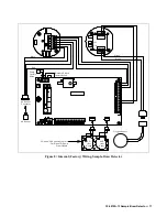
Figure 8:  Internal (Factory) Wiring, Sample-Draw Detector

W hit e

SPAN

Z ER O

G

OX Y

BK

W

R D

OX Y

T OX IC

T OX IC

24 V

4/2 0

+

+

F B

TP

 -

B A TT

TP

 +

Pressure S w itc h
F actory W ired

H2S

(Not

Used)

CO

(N ot

Used)

Pum p
F actory
W ired

G reen

W hit e

R ed

H2 S ensor

C onnector

H2 S ensor

G reen

Black

CO and H2S S ensors Plug I nto

F ar S ide of P reamp

Circuit B oard

IN

S

T

R

U

M

EN

T

S

SE

N

S

O

R

G RN

T P -

B L K

S P AN Z E RO

PO

W

E

R

/S

IG

P /N 57 -10 50RK

RE V . 0

T P +

G ND

2 4V

4 -2 0

R E D

W H T

O xy gen S ensor

Summary of Contents for 35-3010A-13

Page 1: ...www rkiinstruments com 35 3010A 13 Sample Draw Detector Part Number 71 0552 Revision P1 Released 4 15 21 ...

Page 2: ...dic calibration and maintenance of the detector is essential for proper operation and correct readings Please calibrate and maintain this detector regularly Frequency of calibration depends upon the type of use you have and the sensor types Typical calibration frequencies for most applications are between 3 and 6 months but can be required more often or less often based on your usage ...

Page 3: ...cement costs local repair costs transportation costs or contingent expenses incurred without our prior approval THIS WARRANTY IS EXPRESSLY IN LIEU OF ANY AND ALL OTHER WARRANTIES AND REPRESENTATIONS EXPRESSED OR IMPLIED AND ALL OTHER OBLIGATIONS OR LIABILITIES ON THE PART OF RKI INSTRUMENTS INC INCLUDING BUT NOT LIMITED TO THE WARRANTY OF MERCHANTABILITY OR FITNESS FOR A PARTICULAR PURPOSE IN NO E...

Page 4: ... Operation 19 Normal Operation 19 Low Flow Alarm 19 Maintenance 20 Preventive Maintenance 20 Troubleshooting 20 Replacing Components of the Sample Draw Detector 21 Adjusting the Low Flow Setting 22 Calibration Frequency 23 Calibration IR CH4 Detector 23 Preparing for Calibration 23 Zeroing with Nitrogen 24 Setting the Response Reading 24 Zeroing with Background Gas 24 Returning to Normal Operation...

Page 5: ... manual to assure proper and safe operation of the 35 3010A 13 and to minimize the risk of personal injury Be sure to maintain and periodically calibrate the 35 3010A 13 as described in this manual Table 1 Specifications Target Gases Detection Ranges Hydrogen H2 0 10 volume Oxygen 0 25 volume Input Power 24 VDC Current Draw 240 mA Output Signals 4 20 mA each channel Construction housing Fiberglass...

Page 6: ...for installation where general purpose equipment is in use The housing door is hinged on the left side and is secured by two latches on the right side Four mounting feet are attached to the back of the housing one at each corner Use the mounting feet Hydrophobic Filter AcroPak H2S Dummy Sensor Amp 1 Pump Charcoal Filter H2 Transmitter Oxygen Transmitter H2 Sensor Oxygen Sensor CO Dummy Sensor Amp ...

Page 7: ...Figure 2 Sample Draw Detector Flow Diagram INLET Fitting The INLET fitting on the bottom of the housing allows the gas sample to enter the sample draw detector The INLET fitting accepts 1 4 in rigid tubing See Installation on page 14 for instructions to connect tubing to the INLET fitting Hydrophobic Filter The hydrophobic filter is to the left of the main circuit board It is held in place by a me...

Page 8: ...ugh the sample draw detector will operate down to a flow of 0 6 SCFH the optimum flow rate is 1 2 SCFH Bypass Valve The bypass valve is to the left of the flowmeter The bypass valve adjusts the flow rate to the sensor Use a flat blade screwdriver to adjust the bypass valve NOTE The bypass valve allows fine adjustments of the flow rate For a wider range of adjustment use the flow adjust potentiomet...

Page 9: ... and electronic reactions these elements produce an electrical output that is proportional to the detection range of the sample draw detector Connector The top of the sensor includes five pins that plug into the socket connector This connector allows you to replace the sensor without disconnecting the wiring The sensor leads are soldered to the connector Sensor Leads Four color coded leads extend ...

Page 10: ...se readings and the zero pot to make adjustments to the zero reading Transmitter Interconnect Terminal Strip The transmitter interconnect terminal strip is the seven point terminal strip near the right edge of the transmitter The transmitter is factory wired to the sensor and main circuit board Test Points The test points are located on the left side of the transmitter and are labeled TP and TP A ...

Page 11: ...Strip The detector terminal strip is the four point terminal strip near the bottom edge of the transmitter It is factory wired to the transmitter Interconnect Terminal Strip The interconnect terminal strip is the four point terminal strip near the top edge of the transmitter It is factory wired to the main circuit board Span Zero Pots The span and zero pots are located on the left side of the tran...

Page 12: ... strip sensor transmitter terminal strip amp 1 circuit amp 2 circuit pump terminal strip relay and reset switch see Figure 5 NOTE The flowmeter and status lights are mounted to the main circuit board but are considered part of the flow system Interconnect Terminal Strip The interconnect terminal strip is the sixteen point terminal strip near the bottom edge of the main circuit board Use the interc...

Page 13: ...and CAL 2 for the H2S channel No output is available at any of the test points Pump Terminal Strip The pump terminal strip is the four point terminal in the top left corner of the circuit board Use the pump terminal strip to connect the pump and pressure switch to the main circuit board NOTE The pump and pressure switch are factory wired to the circuit board See Installation on page 14 for all wir...

Page 14: ...m to open the housing door and make wiring connections at the bottom of the housing and tubing connections at the right of the housing Make sure there is sufficient room to perform start up maintenance and calibration procedures Figure 6 Outline and Mounting Dimensions 2 Close and latch the housing door NOTE The sample draw detector is shipped with the mounting feet tucked under the housing to pro...

Page 15: ...the EXHAUST fitting 4 Route the opposite end of the tubing to an open area where the sample can safely disperse Wiring the Sample Draw Detector WARNING Always verify that the power source is OFF before you make wiring connections 1 Turn off the controller 2 Turn off or unplug incoming power to the controller 3 Unlatch and open the housing door of the sample draw detector 4 Guide a six conductor 18...

Page 16: ...7 External Field Wiring Sample Draw Detector 4 20 Feedback Interconnect Terminal Strip LEL Controller Transmitter Terminals 24 VDC 24 VDC 4 20 Feedback Reset Switch Ox ygen Controller Transmitter Terminals Main Circuit Board Sample Draw Housing ...

Page 17: ...0 F B T P BATT T P Pressure Switch Factory W ired H2S Not Used CO Not Used Pum p Factory W ired Green W hite Red H2 Sensor Connector H2 Sensor Green Black CO and H2S S ensors Plug Into Far Side of P reamp Circuit Board I NS TRU M EN TS S E NS O R G RN T P BL K SP AN Z E RO P OW E R S IG P N 57 10 50RK RE V 0 T P G ND 2 4V 4 2 0 RE D W H T Oxygen Sensor ...

Page 18: ...incoming sample line is not leaking 8 Remove your thumb from the sample line press the pump reset switch and verify the flowmeter returns to a normal flow rate Setting the Zero Reading CAUTION If you suspect the presence of combustible gas or an abnormal oxygen condition not 20 9 in the monitoring environment use the calibration kit and the zero air calibration cylinder to introduce fresh air to t...

Page 19: ...s 434 mV 2 mV 9 For H2 Disconnect the sample tubing from the sample draw detector s inlet line Unscrew the regulator from the calibration cylinder 10 Close the housing door Operation Normal Operation During normal operation the Pilot LED will be on and the flowmeter will indicate about 1 2 SCFH The current gas readings will be indicated at the controller See the controller s operator s manual for ...

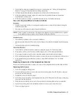
Page 20: ...nt changes in the reading Quarterly Calibrate the sample draw detector as described in Calibration H2 Detector on page 23 and Calibration Oxygen Detector on page 26 Troubleshooting The troubleshooting guide describes symptoms probable causes and recommended action for problems you may encounter with the sample draw gas detector NOTE This troubleshooting guide describes sample draw detector problem...

Page 21: ...ample draw detector is malfunctioning Recommended Action 1 Verify that the calibration cylinder contains an adequate supply of a fresh test sample 2 If necessary set the correct flow rate with the bypass valve or flow adjust potentiometer 3 If you cannot set the correct flow rate check the sample line for obstructions or kinks 4 If the calibration response difficulties continue replace the sensor ...

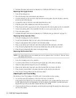
Page 22: ...ve the filter 5 Place the new hydrophobic filter in the same orientation as the one that was removed 6 Place the new hydrophobic filter back into the metal clamp Replacing the Charcoal Filter NOTE The charcoal filter does not normally need to be replaced in the 35 3010A 13 because it does not include a CO sensor 1 Turn off or unplug power to the controller 2 Locate the charcoal filter It is locate...

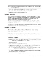
Page 23: ...onment is not well controlled then more frequent calibration than every 9 months may be necessary Calibration H2 Detector This section describes how to calibrate the H2 sensor in the sample draw detector It includes procedures to prepare for calibration zero with nitrogen set the response reading zero with background gas and return to normal operation NOTE This procedure describes calibration usin...

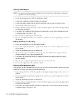
Page 24: ... line at or near the sample draw detector s INLET fitting 3 Allow the calibration gas to flow for one minute 4 Check the mV output on the H2 transmitter test points and verify that the reading matches the response reading 2 mV you determined earlier 5 If necessary use the span pot on the H2 transmitter to adjust the reading to match the correct response reading 6 Disconnect the sample tubing from ...

Page 25: ...onvenience leave the regulator connected to the sample tubing Returning to Normal Operation 1 Remove the voltmeter leads from the test points 2 Reconnect the incoming sample line 3 Wait 1 to 2 minutes to allow the calibration gas to be drawn out and the reading to stabilize 4 Close the housing door 5 Store the components of the calibration kit in a safe and convenient place ...

Page 26: ... the calibration kit sample tubing to the regulator 3 Connect the sample tubing from the regulator to the inlet line at or near the sample draw detector s INLET fitting 4 Allow the sample draw detector to respond to the calibrating sample for approximately 1 minute 5 After one minute check the mV output on the oxygen transmitter test points and verify a reading of 100 mV 2 mV 6 If necessary use th...

Page 27: ...n kit in a safe and convenient place Parts List Table 4 lists replacement parts and accessories for the sample draw gas detector Table 2 Parts List Part Number Description 06 1248RK Sample tubing 3 16 x 5 16 specify length for calibration kit 30 0610RK Pump 33 0171RK Hydrophobic filter AcroPak 33 6095RK Charcoal filter CF 188 65 0601RK Oxygen sensor 81 0022RK 01 Calibration cylinder 4 volume H2 in...

Reviews: