IMR01H01-E4
15
6.4 Transfer of Control Area
The memory area used for this control (control area) can be
selected by contact input (option) or communication (option)
other than the key operation. The memory area transfer by
contact input and the key operation is shown in the following.
When the memory area is transferred by communication, see
the
Communication Instruction Manual (IMR01H02-E
!
).
"#
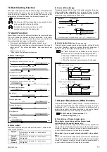
Control area transfer by key operation
When the control area is changed from memory area number
1 to 3.
1.
Press the SET key in PV/SV
monitor mode state to transfer
to SV setting & CT monitor
mode.
2.
Press the SET key to change
the display to
ArE
(memory
area transfer display).
3.
Press the UP key to change to
3
.
4.
Press the SET key to register
the value thus set. The AREA
display shows the memory area
number
3
. (The figure at left
shows the current transformer 1
monitor display)
For memory area numbers, the number changed last is
effective.
The memory area number (control area) can be
changed at either RUN or STOP.
"#
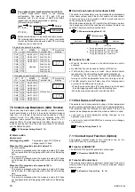
Control area transfer by contact input (Option)
The control area can be selected according to the open or close
state of the terminal numbers 39 to 43. The memory area
number is selected according to the open or close state of the
terminal number 39 to 42, and the selected memory area
number is registered when the terminal number 39 and 43 (DI
SET) changes from the open state to the close state.
Terminal
No.
1
2
3
4
5
6
7
8
39 - 40
×
−
×
−
×
−
×
−
39 - 41
×
×
−
−
×
×
−
−
39 - 42
×
×
×
×
−
−
−
−
×
: Contact open
−
: Contact closed
After the contact is closed, it takes a short time* until
the action of this device is actually selected. Therefore,
pay attention to this delay time if the device is used
together with a sequencer, etc.
*
S
elect the area in a period 0.5 seconds after the DI SET
terminals are closed.
6.5 Autotuning (AT)
The AT function automatically measures, computes and sets the
optimum PID and LBA constants. If the AT function is activated,
the optimum PID constants concerning the set value (SV) in the
control area and the LBA setting time can be automatically set
(Limit cycle system is adopted). This function is activated power-
ON, during temperature rise and/or when control is stabilized from
any process state. The result obtained by AT is reflected to the
parameters (P, I, D and LBA) of the parameter setting mode.
"#
AT start
$#
Start AT when all following conditions are satisfied:
-
Prior to starting the AT, end all the parameter settings other
than PID and LBA.
-
Both the lock level 1 and the lock level 2 should be set to
0000
.
-
RUN/STOP is in the RUN mode.
$#
Procedure:
1.
Change the mode to the setup
setting mode to show the
execution of autotuning (AT)
display.
2.
Press the UP key to change to
on.
3.
Press the SET key.
After this function is executed,
the autotuning lamp flashes.
When the AT is finished, the execution of autotuning
(AT) will automatically return to show
oFF
(AT lamp
OFF).
"#
AT cancellation
The AT is canceled if any of the following conditions exist:
•
When the SV is changed
•
When the PV bias value is changed
•
When the PV becomes abnormal when burnout occurs
•
When the AT does not end in nine hours after AT started
•
When the power is turned off
•
When the RUN/STOP is changed to the STOP mode
•
When a power failure longer than 30 ms occurs
•
When the control area is changed
If the AT is canceled, the controller immediately
changes to PID control. The PID and LBA constants will
be the same as before AT was activated.
When AT is competed, the controller immediately
changes to PID control. If the control system does not
allow the AT cycling process, do not use AT and set
each PID constant to meet the needs of the application.
Memory area number
PV
CH
SV
AREA
PV
CH
SV
AREA
39
40
DI1
41
DI2
42
DI4
43
DI SET
PV
CH
SV
AREA
PV
CH
SV
AREA
PV
CH
SV
AREA
PV
CH
SV
AREA


