background image

Page 10 of 30                                 20160927-Ver.1  

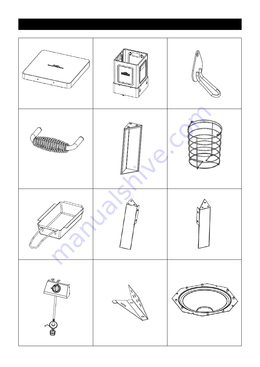
COMPONENT LIST


1. Lid Assembly 

2. Body Assembly 

3. Match Hole Cover 


Qty: 1pc 

Qty: 1pc

Qty: 4pcs

4. Lid Handle, Silver 

5. Rear Leg 

6. Basket 


Qty: 1pc 

Qty: 2pcs

Qty: 1pc

7. Grease Tray 

8. Front Left Leg 

9. Front Right Leg 


Qty: 1pc 

Qty: 1pc

Qty: 1pc

10. Control Panel And Regulator 

Assembly 

11. Flame Tamer 

12. Grease Collector 


Qty: 1pc   

Qty: 4pcs 

Qty: 1pc 

Summary of Contents for TF2201802-RG

Page 1: ...reference This instruction manual contains important information necessary for the proper assembly and safe use of the appliance Read and follow all warnings and instructions before assembling and us...

Page 2: ...re department Failure to follow these instructions could result in fire or explosion which could cause property damage personal injury or death DANGER 1 Never operate this appliance unattended 2 Never...

Page 3: ...is not intended to be installed in or on a boat This appliance is not intended to be installed in or on recreational vehicles This appliance shall not be used on or under any apartment or condominium...

Page 4: ...y in some circumstances contain fire When cooking the appliance must be on a level stable noncombustible surface in an area clear of combustible material An asphalt surface may not be acceptable for t...

Page 5: ...appliance until it is cool to touch Keep appliance area clear and free from combustible materials gasoline and other flammable vapors and liquids Keep LP cylinder at a minimum distance of 24 inches 61...

Page 6: ...rements 12 30 5cm diameter x 18 45 7cm tall with 20lb 9 1kg capacity maximum Q C C Type 1 outlet compatible with regulator or appliance Safety relief valve UL listed Overfill Protection Device OPD Thi...

Page 7: ...sert any foreign objects into the valve outlet Damage to the valve outlet could result A damaged valve outlet can cause a leak possibly resulting in explosions fire severe bodily harm or death WARNING...

Page 8: ...se a soapy water solution to check all connections for leaks a Leak Test before attempting to light the appliance see P 20 21 If a leak is found turn the cylinder valve off and do not use the applianc...

Page 9: ...Page 9 of 30 20160927 Ver 1 PRODUCT DIAGRAM...

Page 10: ...atch Hole Cover Qty 1pc Qty 1pc Qty 4pcs 4 Lid Handle Silver 5 Rear Leg 6 Basket Qty 1pc Qty 2pcs Qty 1pc 7 Grease Tray 8 Front Left Leg 9 Front Right Leg Qty 1pc Qty 1pc Qty 1pc 10 Control Panel And...

Page 11: ...Page 11 of 30 20160927 Ver 1 13 Meat Thermometer 14 Lifting Hook 15 Fryer Handle Black Qty 1pc Qty 1pc Qty 2pcs REPLACEMENT PART LIST I...

Page 12: ...e Silver 5 Rear Leg 6 Basket 7 Grease Tray 8 Front Left Leg 9 Front Right Leg 10 Control Panel And Regulator Assembly 10a Orifice Nut 10b Orifice Bracket 10c Control Panel 10d Knob Bezel 10e Control K...

Page 13: ...EDURES Step 1 Attach the Rear Leg 5 Front Left Leg 8 and Front Right Leg 9 to the Body Assembly 2 by using 12 pcs M6x8mm Bolt A Step 2 Attach the Control Panel And Regulator Assembly 10 to the front l...

Page 14: ...the bottom of body assembly by using 2 pcs M6x8mm Bolt A as shown Make sure that the valve outlet orifice is inserted STRAIGHTLY into the burner port Step 4 Insert the terminal of ignition wire into...

Page 15: ...1 Step 5 Attach the Match Hole Covers 3 to the body assembly by using 4 pcs M6 Step Bolt B Make sure that the covers can swing smoothly Step 6 Attach the Fryer Handle Black 15 to the body assembly by...

Page 16: ...Ver 1 Step 7 Attach the Lid Assembly 1 to the body assembly by using 2 pcs Hinge Pin C and 2 pcs Cotter Pin D Step 8 Attach the Lid Handle Silver 4 to the lid by using 2 pcs M6x8mm Bolt A and 4 pcs He...

Page 17: ...the bottom of the body assembly as shown Suggest using a disposable aluminum tray as a liner Step 10 Position the Grease Collector 12 into the fryer body and make sure that it is fixed by 4 guiding pi...

Page 18: ...Page 18 of 30 20160927 Ver 1 Step 11 Place the Flame Tamer 11 into the guiding pins on the grease collector as shown Step 12 Place the Basket 6 into the fryer body on the grease collector as shown...

Page 19: ...our unit is fully assembled Make sure to read and follow the Instruction Manual before using this appliance When transporting or storing the appliance without tank attached hook the regulator onto the...

Page 20: ...MOKE WHILE CONDUCTING LEAK TEST NEVER PERFORM LEAK TEST WITH AN OPEN FLAME If it is evident that there is excessive abrasion wear or the hose is cut it must be replaced prior to the appliance being pu...

Page 21: ...esent Only the pressure regulator and hose assembly supplied with the unit should be used Perform the LEAK TEST according to the instructions before operating the appliance ALWAYS keep your face and b...

Page 22: ...GHTING 1 Open the lid and make sure control knob is in OFF position 2 Turn ON gas valve from cylinder 3 Swing match hole cover to expose match lighting hole Place lit match into match lighting hole of...

Page 23: ...away from the burner it indicates too much air If any of these conditions exist call our customer service line Visually check the burner flames prior to each use The flames should look like this pict...

Page 24: ...paint Never apply paint to the interior surface Rust spots on the interior surface can be buffed cleaned and then lightly coated with vegetable oil or vegetable oil spray to minimize rusting GREASE TR...

Page 25: ...he smell of gas in conjunction with the burner flames appearing yellow 2 The appliance does not reach temperature 3 The appliance heats unevenly 4 The burner makes popping noises WARNING ENSURE that t...

Page 26: ...center the burner over the orifice as shown at below diagrams TO REINSTALL THE BURNER 1 Place the burner into the main body and insert the ignition wire through the hole on the bottom panel of the fir...

Page 27: ...internal food temperatures Chill Refrigerate prepared foods and leftovers promptly HOW TO VERIFY IF MEAT IS COOKED COMPLETELY Meat and poultry cooked in the appliance often browns very fast on the out...

Page 28: ...ner holes may be obstructed 2 Unit is not sufficiently preheated 3 Burner is improperly seated on control valve 1 Refer to section of Burner Cleaning at P 26 to clean the burner 2 Preheat the unit for...

Page 29: ...S OF TIME LOSS OF FOOD INCONVENIENCE EXPENSES FOR TRAVEL TRANSPORTATION LODGING EXPENSES LOSS BY DAMAGE TO PERSONAL PROPERTY OR LOSS OF INCOME PROFITS OR REVENUE 6 MANUFACTURER S OBLIGATION Manufactur...

Page 30: ...less Fryer Roaster Cover Should you encounter any problem or Obtaining replacement parts CALL US FIRST Do not return product to the store WE CAN HELP Rankam China Manufacturing Co Ltd 18 F New Lee Wah...

Reviews: