71
Operating and Maintenance Instructions – 7 Hardware and software
Rittal Liquid Cooling Package Plus
7
Hardware and
software
7.1
Liquid Cooling Package
Plus control unit
7.1.1 Hardware
A Basic CMC forms the control unit of the Liquid Cooling Package Plus. Its job
is to use the I
2
C bus to poll the measurements (such the three server-in tempe-
ratures, three server-out temperatures, six fan speeds, flow rate, control valve
position, flow and return temperatures of the cooling water) from the six fan mo-
dules, the sensors on the heat exchanger, and from the water module, to per-
form control functions, and to transfer the setpoints (such as the fan speed) to
the individual units.
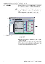
Fig. 64:
Control unit Liquid Cooling Package (Basic CMC) – front
1
Button "C"
2
Status LED (alarms and warnings)
3
Status LED (network status)
4
Hyperterminal
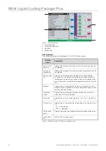
The control circuit board is built into a standard CMC plastic housing. The fol-
lowing components are on the front side of the unit:
Control
component
Explanation
Button "C"
Use this button to confirm warnings and alarms as well as to set
the setpoint for the desired cold air temperature.
Status LED:
(alarms and
warnings)
Displays the internal status of the control unit through a duo LED
(red/green). The various alarm and warning conditions can be
shown via this LED.
Status LED:
(network
status)
Displays the status of the network connection.
CMC - TC
!
C
Basic CMC
IOIOI
1
2
3
4

