12.
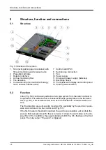
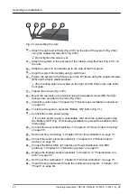
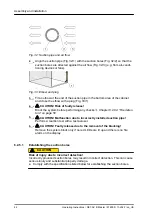
Attach the right and left rails (Fig. 23/3) on the side of the system (Fig. 23/4)
using the supplied screws (M4, Fig. 23/5).
Do not tighten the screws yet.
13.
Attach the system in the rear area of the cabinet using the hook (Fig. 23/1) on
the rails.
14.
Slide the system in horizontally up to the stop of the front panel.
15.
Align the system horizontally using a spirit level.
16.
Fasten the system to the front panel in the 19" frame using the supplied screws
(M6) and the black plastic washers.
The mounting holes are located on the right and left of the outer side of the
front plate.
17.
Tighten the screws (Fig. 23/5).
18.
Mount the rear rails on the cabinet using the supplied screws (M5). Nuts for
doing so are provided in the rails (Fig. 23/2).
19.
Chapter 6.2.5 “Suction pipe installation instructions”
20.
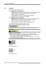
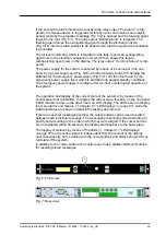
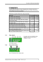
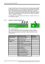
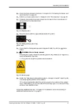
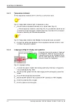
To start up the system, press the "Battery ON" button (Fig. 21).
21.
Connect the mains power supply.
If a mains power supply is unavailable, shut down the system again using
the "Battery OFF" (Fig. 21) following installation to prevent the batteries from
discharging.
22.
Connect the door contact switches
Chapter 6.3.5 “Door contact / blocking”
23.
Set the air flow monitoring
Chapter 8.6 “Air flow calibration” on page 73
24.
Connect the alarm elements (optional)
25.
Connect the Rittal CMC, IoT interface or Power Distribution Unit PDU
(optional)
Chapter 6.3.3 “Monitoring system” on page 54
26.
Engage the floating contacts (optional)
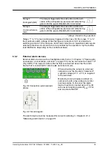
Chapter 6.3.1 “Potential-free con-
27.
Set the air flow calibration
Chapter 8.6 “Air flow calibration” on page 73
28.
Import the set parameters through the maintenance program
1
2
3
4
5
Fig. 23: Assembling the rails
Assembly and installation
Operating Instructions / DET-AC III Master / 916005 / 11-2022 / en_US
40

