


Operation
UPS-Manual
20
EN
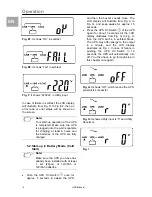
5.4. UPS Default Data and Special
Function Execution
•
After the UPS completes start up, press
key pad to change the LCD display
screen to Fig. Q1.
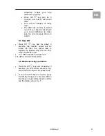
Fig. Q1
: It shows buzzer “On”
Fig. Q
: It shows buzzer “Off”
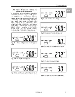
•
Press key pad to scroll down the
screen and check the UPS settings. The
LCD display will subsequently show: Fig.
Q1 (buzzer)
Æ
Fig. R1 (Self-test)
Æ
Fig.
S1 (Bypass Voltage Windows)
Æ
Fig. T
(Output Frequency Synchronization
Window)
Æ
Fig. U (Inverter Output
Voltage)
Æ
Fig. V1 (UPS Operation
Mode)
Æ
Fig. W (Output Voltage Micro
Tune Value)
Æ
Fig. X (UPS Id)
Æ
Fig. Y
(No. of UPS in Parallel).
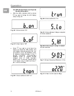
Fig. R1
: It shows self-test is NOT “on”
Fig. R2
: It shows self-test is “On”
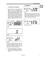
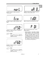
Fig. S1:
It shows Bypass Voltage is adjusted
to narrow tolerance
Fig. S2:
It shows bypass voltage is adjusted
to wider tolerance
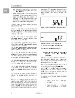
Fig. T
: It shows Frequency Window is +/-3Hz
Fig. U
: It shows inverter output voltage