


4.1. Password Protection
Password protection can be enabled to prevent unauthorised access to set-up
screens, by default password protection is not enabled.
Password protection is enabled by selecting a four digit number other than 0000,
setting a password of 0000 disables the password protection.
4. Programming
The following sections comprise step by step procedures for configuring the
meter
for individual user requirements.
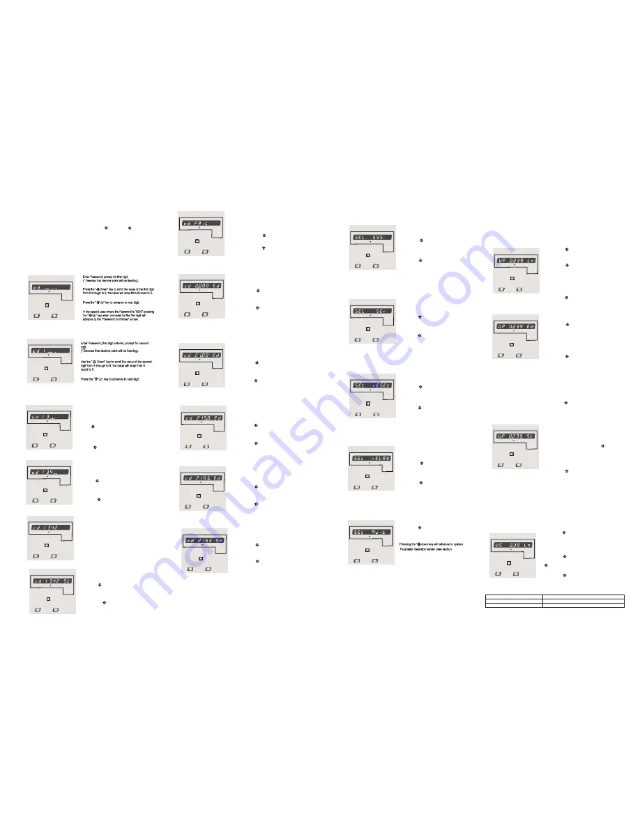
To access the set-up screens press and hold the “
Key simultaneously for 5 seconds. This will take the User into the Password
Protection Entry Stage (Section 4.1).
Down” and “ Up”
Enter Password, second digit entered, prompt for third
digit.
(* Denotes that decimal point will be flashing).
Use the “ Down” key to scroll the value of the third
digit from 0 through to 9, the value will wrap from 9
round to 0.
Press the “ Up” key to advance to next digit.
Enter Password, third digit entered, prompt for fourth
digit.
(* Denotes that decimal point will be flashing).
Use the “ Down” key to scroll the value of the fourth
digit from 0 through to 9, the value will wrap from 9
round to 0.
Press the “ Up” key to advance to verification of the
password.
Enter Password, fourth digit entered, awaiting
verification of the password.
Password confirmed.
Pressing “ Down” key will advance to the “New /
change Password” entry stage.
Pressing the “ Up” key will advance to the Menu selection
screen. (See section 4.2).
Password Incorrect.
The unit has not accepted the
Password entered.
Pressing the "
Down" key will return to
the Enter Password stage.
Pressing the “ Up” key exits the
Password menu and returns operation
to the measurement reading mode.
3
4
x1000
kWh
V
ON
I
REV
x1000
kWh
V
ON
I
REV
x1000
kWh
V
ON
I
REV
x1000
kWh
V
ON
I
REV
x1000
kWh
V
ON
I
REV
x1000
kWh
V
ON
I
REV
x1000
kWh
V
ON
I
REV
New / Change Password
(*Decimal point indicates that this will be flashing).
Pressing the “ Down” key will scroll the value of the
first digit from 0 through to 9, the value will wrap from 9
round to 0.
Pressing the “ Up” key to advance the operation to
the next digit and sets the first digit, in this case to “2”
New / Change Password, first digit entered, prompting for
second digit. (*Decimal point indicates that this will be
flashing).
Pressing the “ Down” key will scroll the value of the
second digit from 0 through to 9, the value will wrap from
9 round to 0.
Pressing the “ Up” key to advance the operation to the
next digit and sets the second digit, in this case to “1”
New / Change Password, second digit entered,
prompting for third digit. (*decimal point indicates that
this will be flashing).
Pressing the “ Down” key will scroll the value of the
third digit from 0 through to 9, the value will wrap from 9
round to 0.
Pressing the “ Up” key to advance the operation to
the next digit and sets the third digit, in this case to “5”
New / Change Password, third digit entered, prompting
for fourth digit. (* denotes that decimal point will be
flashing).
Pressing the “ Down” key will scroll the value of the
fourth digit from 0 through to 9, the value will wrap from
9 round to 0.
Pressing the “ Up” key to advance the operation to
the “New Password Confirmed” and sets the fourth digit,
in this case to “3”.
New Password confirmed.
Pressing the “ Down” key will return to the
“New/Change Password”.
Pressing the “ Up” key will advances to the
Menu selection screen.(see section 4.2).
This menu screen will allow the user to select different
Parameter related to Relay Output.
Pressing the “ Up” key allows the user to select &
Configuare the relay output option (see section 4.2.4.1)
(see section 4.2.5)
Pressing the “ down key will advance to Quit screen.
4.2.5 Quit screen.
4.2.4 Relay Output Parameter selection screen.
4.2 Menu selection.
This menu screen is used to select the different system
Parameter like “system type,””CT Ratio”,”PT Ratio”,
Pressing the “ Up” key allows the user to set
Pressing the “ down” key will advance to
Different system parameters.
Communication selection screen (see section 4.2.2)
4.2.2 Communication Parameter selection screen.
4.2.3 Reset Parameter selection screen.
4.2.1 System Parameter selection screen.
This menu screen is used to Reset the energy parameter .
Pressing the “ Up” key allows the user to Reset energy
Pressing the “ down key ” will advance to Output
system parameter (see section 4.2.3.1)
Option selection screen (see section 4.2.4).
This menu screen is used to select the different communication
parameters like “Address selection”,”RS485 Parity selection”,
Pressing the “ Up” key allows the user to set different
Pressing the “ down key will advance to Reset parameter
Communication parameters
(see section 4.2.3)
”RS485 baud rate”
Screen.
Pressing the “ Up” key will allow the user to Quit from menu
& return to measurement screen.
(see section 4.2.1.1 to 4.2.1.3)
(see section 4.2.2.1 to 4.2.2.3)
This screen allows user to Quit from Menu.
x1000
kWh
V
ON
I
REV
x1000
kWh
V
ON
I
REV
x1000
kWh
V
ON
I
REV
x1000
kWh
V
ON
I
REV
x1000
kWh
V
ON
I
REV
x1000
kWh
V
ON
I
REV
x1000
kWh
V
ON
I
REV
x1000
kWh
V
ON
I
REV
x1000
kWh
V
ON
I
REV
x1000
kWh
V
ON
I
REV
4.2.1)
4.2.1 System parameters Selection
Pressing the “ Up” key accepts the present value
and advances to the “potential Transformer secondary
Value edit” menu. (See Section 4.2.1.2)
Pressing the “ Down” key will enter the “Potential
Transformer Primary Value Edit” mode.
Initially the “multiplier must be selected, pressing the “
Down” key will move the decimal point position to the
right until it reaches # # # .# after which it will return to
#. # # #.
Pressing the “ Up” key accepts the present
multiplier (decimal point position) and advances to the
“
Digit Edit” mode.
potential Transformer primary
4.2.1.1 Potential Transformer Primary Value
This screen enables the user to set primary transformer voltage
In terms of kilovolts (note the x1000 enunciator).
Potential Transformer primary Digit Edit
Pressing the “ Down” key will scroll the value of
the most significant digit from 0 through to 9 unless
the presently displayed Potential Transformer Primary
Value together with the Current Transformer Primary
Value, previously set, would result in a maximum power
of greater than 1000 MVA per phase in which case
the digit range will be restricted.
Pressing the “ Up” key accepts the present value
at the cursor position and advances the cursor to the
next less significant digit.
Note : the flashing decimal point indicates the cursor position, a steady decimal point will be present
to identify the scaling of the number until the cursor position coincides with the steady decimal point
position. At this stage the decimal point will flash.
When the least significant digit has been set pressing the “ Up” key will advance to the
“Potential Transformer Primary Value Confirmation” stage.
Screen showing display of 0.239 kV i.e. 239 Volts indicating steady decimal point and cursor
flashing at the “hundreds of volts” position.
Potential Transformer Primary Value Confirmation
This screen will only appear following an edit of the
Potential Transformer Primary Value.
If the scaling is not correct, pressing the “ Down”
key will return to the “Potential Transformer Primary
Value Edit” stage.
Pressing the “ Up” key sets the displayed value
and will advance to the Potential Transformer secondary
Value (See Section 4.2.1.2)
x1000
kWh
V
ON
I
REV
x1000
kWh
V
ON
I
REV
x1000
kWh
V
ON
I
REV
4.2.1.2 Potential Transformer secondary Value
The value must be set to the nominal full scale secondary voltage which will be obtained from the
Transformer when the potential transformer(PT)primary is supplied with the voltage defined in 4.2.1.1
potential transformer primary voltage. The ratio of full scale primary to full scale secondary is defined
as the transformer ratio.
Note that the range of instrument is from 140 to 277V
Transformer Secondary Value Edit” mode. Pressing the
“ Down” key will scroll the value of the most significant digit
From available range of PT secondary value
Pressing the “ Down” key will enter the “Potential
Pressing the “ Up” key accepts the present value
and advances to the “Current Transformer Primary
Value edit” menu. (See Section 4.2.1.3)
Pressing the “ Up” key accepts the present value
at the cursor position and advances the cursor to the
next less significant digit.
for 239 VL-N. Please refer the table below for different ranges.
Potential Transformer secondary ranges for various Input Voltages
63.5V L-N
57V - 69V L-N
70V - 139V L-N
140V - 277V L-N
133.0V L-N
239.6V L-N
x1000
kWh
V
ON
I
REV
3600 Imp/KWh
3600 Imp/KWh
3600 Imp/KWh
3600 Imp/KWh
3600 Imp/KWh
3600 Imp/KWh
3600 Imp/KWh
3600 Imp/KWh
3600 Imp/KWh
3600 Imp/KWh
3600 Imp/KWh
3600 Imp/KWh
3600 Imp/KWh
3600 Imp/KWh
3600 Imp/KWh
3600 Imp/KWh
3600 Imp/KWh
3600 Imp/KWh
3600 Imp/KWh
3600 Imp/KWh
3600 Imp/KWh
3600 Imp/KWh


