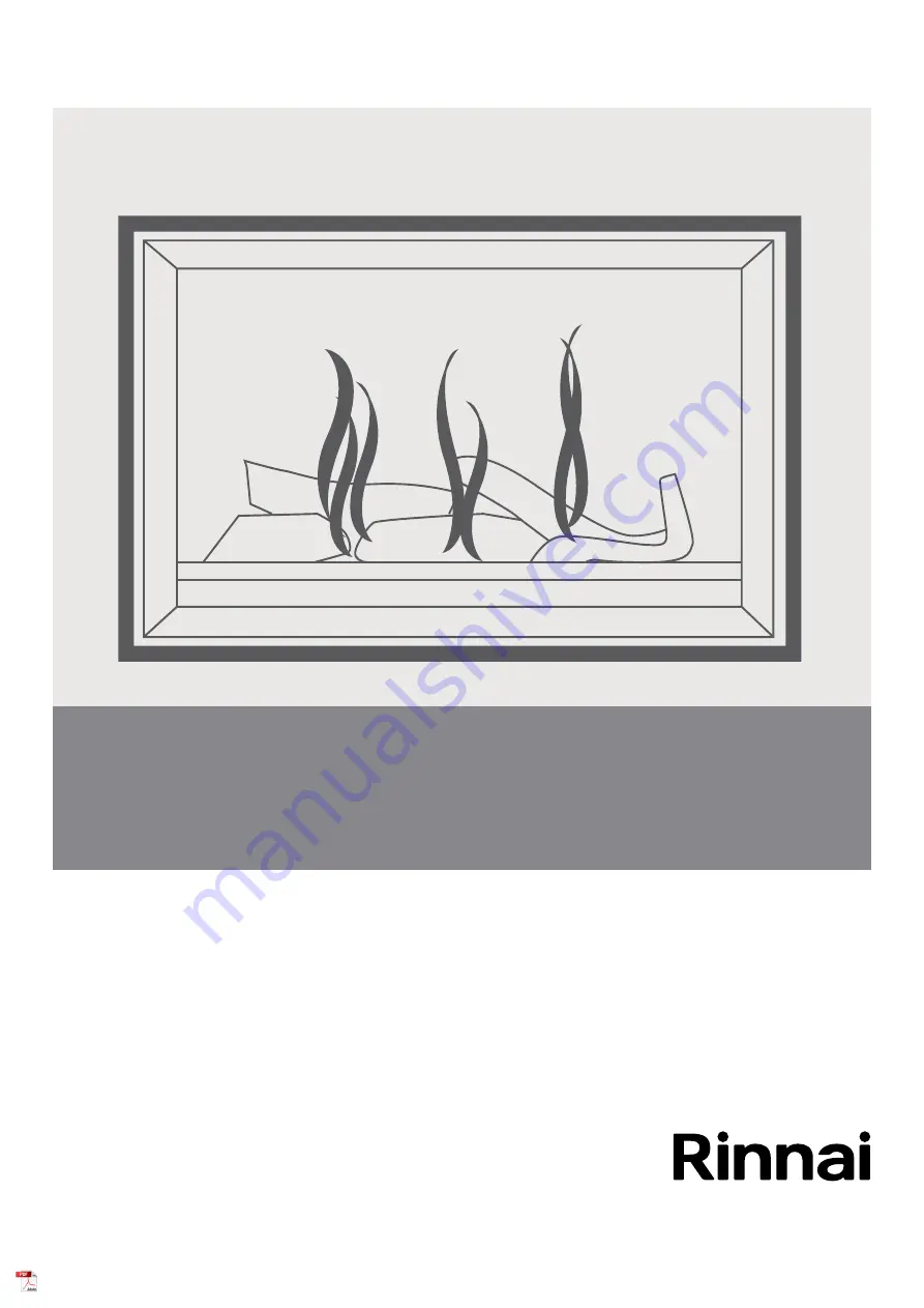
Symmetry gas fireplace
Installation guide
Models:
RDV3611ETRN / RDV3611ETRL
Page 1: ...Symmetry gas fireplace Installation guide Models RDV3611ETRN RDV3611ETRL...
Page 2: ...on servicing and repair shall be carried out only by authorised personnel Warning Improper installation adjustment alteration service or maintenance can cause property damage personal injury or loss o...
Page 3: ...uidelines 22 Flueing options 24 Symmetry RDV3611 flue kits 26 Symmetry RDV3611 horizontal flue kits 27 Symmetry RDV3611 flue components 28 Horizontal termination example 30 Vertical termination exampl...
Page 4: ...1 5 m power cord and 3 pin plug The standard electrical connection is to the right hand side of the appliance Safety devices Light to pilot delayed ignition overheat switch electronic flame failure s...
Page 5: ...Electrical supply The Symmetry is fitted with a 1 5 m power cord and a 3 pin plug The standard electrical connection is to the right side of the front of the appliance If necessary this can be change...
Page 6: ...ing installed the width would need to be 1350 1375 mm This additional clearance is required to ensure the ducting does not come into contact with the fire The main points governing location are fluein...
Page 7: ...contact with the heater The 400 mm side clearance includes side walls Floor protection Heat emanating from this fire may over time affect the appearance of some materials used for flooring such as ca...
Page 8: ...low diagram is to assist people who are determining the clearance area around the Symmetry without having the unit on site Glass width 900 mm 400 mm 400 mm 600 mm 400 mm Clearance Clearance Minimum ab...
Page 9: ...00 mm dimension The 400 mm dimension is the minimum clearance required to a mantel The image adjacent shows the dimension from the edge of the frame in the case of the Symmetry the 400 mm dimension is...
Page 10: ...ps may vary Build the frame and complete the electrical connection Install mounting brackets the Symmetry unit and fix the unit to the frame Install the flue and complete the gas connection Install du...
Page 11: ...t up against the framing plate of the fire The metal mounting brackets can be adjusted 20 mm to allow for the different cladding thicknesses Granite or metal frame Bracket is in the forward position a...
Page 12: ...rovide the 150 mm vertical clearance to the upper lintel 3 Fix the unit to the frame with the four mounting brackets These act as seismic constraints as well as providing horizontal clearance to the f...
Page 13: ...ing Cladding support bracket Front of heater Cladding Cladding support bracket Front of heater Cladding MUST NOT extend lower than the cladding support bracket IMPORTANT Detailed view showing cladding...
Page 14: ...gurations require different positioning of the flue restrictor refer to p 24 25 to determine what setting is required 1 2 4 3 1 2 4 3 2 2 3 3 The different hole positions are shown in the diagram Thes...
Page 15: ...tly IMPORTANT It is important to place the pieces in the correct position Incorrect placement can create carbon build up and affect performance Malfunctioning due to incorrect log rock placement is no...
Page 16: ...bent log over the u shaped log and the whale tail log there are pockets underneath to help position it properly For correct positioning ensure that the top bent log is located on the three points show...
Page 17: ...point screw and attach a manometer 4 Using the manual control switch on the appliance turn the unit on and switch to the HIGH setting and adjust the pressure as necessary 5 Disconnect the solenoid yel...
Page 18: ...with the fire such as blocked gas injectors or log set that may have shifted There are some warning signs that could indicate a problem Unusual smell from the appliance Continued difficulty or delay...
Page 19: ...ions For steps on how to install the frame refer to the separate installation instruction provided with each frame kit Installation checklist and customer handover Complete the installation checklist...
Page 20: ...Control Sparker Earth Flame Rod Sparker 5 4 2 3 1 1 2 CONTROL PANEL RECEIVER CONTROL UNIT IGNITION PACK 579 DBC SIT FAN MOTOR 10 9 8 7 6 Modulating Coil 50 Hz High Speed OH SWITCH 2 1 ACTIVE NEUTRAL A...
Page 21: ...Symmetry RDV3611 installation guide 11156 H 08 21 21 Symmetry flueing...
Page 22: ...maintains a 70 mm air space around the hot section of the inner flue protection of a combustible surface is automatically maintained The only additional clearance required is 10 mm from the outer flu...
Page 23: ...zontal run of flue pipe must have a 20 mm rise for every 1 m of run towards the flue termination Never allow the flue pipe to run downwards towards the horizontal flue terminal A downward slope can tr...
Page 24: ...r Restrictor position 2 Min 0 9 m 4 2 m Max 5 4m 1 8 m 3 0 m No restrictor Min 0 6 m after bend Restrictor position 3 Restrictor position 4 Max 3 5 m Restrictor position 3 Restrictor position 4 Restri...
Page 25: ...03 Vertical 0 52 Max Horizontal Vertical 0 692 Max 1 2 m No restrictor Restrictor position 3 Restrictor position 3 Restrictor position 4 The shaded regions determine the position of the flue restrict...
Page 26: ...1 Flue pipe 900 mm x 1 2 Elbow 90 x 1 3 Flue pipe 300 mm x 1 4 Horizontal flashing kit x 1 5 Wall terminal x 1 RDV3611 Flue Kit Horizontal B long R3661 1 Flue pipe 900 mm x 1 2 Elbow 90 x 1 3 Flue pip...
Page 27: ...gth and or kit you may need 25 D 1775 310 1040 325 440 Base 310 D 435 550 Base 25 RDV3611 Short Horiz Flue Kit A R3660 RDV3611 Long Horiz Flue Kit B R3661 Distance from the appliance to the cowl Flue...
Page 28: ...to 175 mm or 360 mm Inner Aluminium Outer Galvanised steel Thru wall plate interior R3645 Interior through wall plate for internal wall passes Centres and ensures suitable clearances from combustibles...
Page 29: ...components used to join the internal flue to the outside flue Refer horizontal wall terminal for installed dimensions Box depth 100 mm Wall strap R3647 Adjustable strap used in interior exterior insta...
Page 30: ...example flue components required 900 mm min vertical rise 540 mm min Symmetry RDV3611 1 Flue pipe 900 mm R3635 2 Wall strap R3647 3 90 bend R3643 4 Flue pipe 5 Horiz flashing kit R3646 6 Horiz wall t...
Page 31: ...ide 11156 H 08 21 31 Vertical termination example flue components required 5 0 0 m m m i n Symmetry RDV3611 540 mm min 5 4 m maximum 1 2 3 2 3 4 1 Flue pipe 150 mm R3630 2 Flue pipe 1200 mm R3636 3 Wa...
Page 32: ...Symmetry RDV3611 installation guide 11156 H Tel 0800 746 624 http www youtube com rinnainz http facebook com rinnainz Rinnai co nz...