Rinnai
3
SMART BOX IM
ASSEMBLY AND APPLIANCE INSTALLATION
CAUTION
The Smart Box Cover and Insert are constructed from durable ABS plastic. Nevertheless, take care
when welding any plumbing connections to ensure no Smart Box parts are subjected to a naked flame
or excessive heat. The Smart Box is
NOT
suitable for installation into walls which are required to be
‘fire resisting’ as defined in the Building Code of Australia (BCA) unless alternative provisions are
made to achieve the required Fire Resistance Level (FRL). Refer to the BCA for more information.
1. The gas, cold water inlet and hot water outlet pipes can be brought through the pipe
entry point at the base of the Insert. The pipe entry point is elevated to prevent water
ingress. This can be sealed if required.
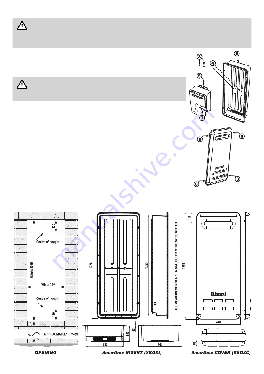
2. Remove the two M5 Nyloc nuts (
3
) from the fixing studs (
4
) of the Insert.
IMPORTANT
Before installing the Rinnai water heater the serial and model numbers
on the data plate located on the left hand side of the appliance MUST
BE copied to the sticker on the inside of the Smart Box Cover. The serial
and model numbers are required for future service work.
3. sert the upper mounting bracket (
5
) of the Rinnai water heater into the bracket slot
(
6
) located at the top of the Insert.
Push the appliance up until the lower mounting bracket (
7
) aligns with the fixing
studs (
4
) and secure in place with the two M5 Nyloc nuts (
3
) removed in step 5.
4. Connect the Rinnai water heater in accordance with the Operation / Installation
manual supplied with the water heater.
5.
An approved weatherproof electrical GPO can be fitted on either side inside the
Insert in accordance with AS/NZS 3000 Wiring Rules and other local requirements.
6. Commission and test the water heater in accordance with the Operation / Installation
manual supplied with the water heater.
Attach the warning sticker that is supplied with these instructions to the front Cover
of the Rinnai water heater.
7.
Install the Smart Box Cover by aligning it with the Smart Box Insert (the flue spigot
hole is to be uppermost) and push into place ensuring that the 4 locking clips (
8
)
have engaged securely.
DIMENSIONS
Top View
Bottum View
Bottum View
Top View


