


11
English
English
CAUTION
• This appliance shall only be serviced by authorized
personnel.
This appliance is to be installed only by an authorized
person according to the current local regulations and
in observation of the manufacturer’s instructions.
• Incorrect installation, for which the manufacturer
accepts no responsibility, may cause personal injury of
damage.
• Always disconnect the cooktop from mains
power supply before carrying out any maintenance
operations or repairs.
WARNING
• We would point out that the adhesive which
bonds the plastic laminate to the furniture must
withstand temperatures not less than 150 to avoid
delamination.
• The appliance must be housed in heat resistant
units.
• The walls of the units must be capable of resisting
temperatures of 75 above room temperature.
INSTALLATION INSTRUCTIONS
A
50mm
from the top of
countertop to
bottom metal cover
68mm
from the top of
countertop to
terminal block
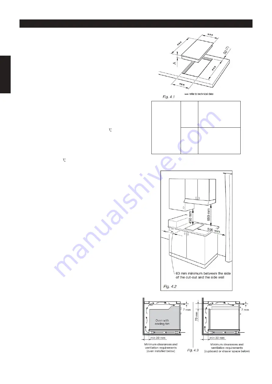
at least 50 mm between the back side of the cut-out
and the back of the countertop
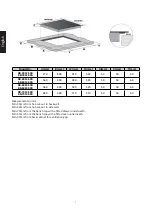
The cooktop can be built into a working surface 30 to
40 mm thick and 600 mm deep.
In order to install the induction hob into the kitchen
fixture, a hole with the dimensions shown in fig.4.1 has
to be made, keeping in consideration of the following:
• The cooktop shall not be installed directly above
a dishwasher, fridge, freezer, washing machine or
clothes dryer, as the humidity may damage the cooktop
electronics.
• If the cooktop is installed above an oven, the oven
shall be provided with cooling fan. The two electrical
supply with independent connections.
IMPORTANT WARNING! This cooktop requires
adequate supply of fresh, cool air to fully function.
The base of the cooktop must have direct unrestricted
ventilation to the room where the cooktop is installed.
Follow the requirements of figure 4.3
• The ceramic hob must be kept no less than 60 mm
away from any side wall.
• The rear wall must be at least 50 mm from the
induction hob.
• There must be a distance of at least 650 mm between
the hob and any wall cupboard or extractor hood
positioned immediately above (see fig. 4.2)
• The coatings of the walls of the unit or appliances
near the cooktop must be heat resistant.