background image

4

OPERATION CONTINUED

Lighting the heater
Once the heater is properly assembled and has

been checked for leaks

it is ready for

operation

.( Refer page 9, To test for gas

tightness.)

1 Place the heater outdoors and ensure that the

minimum clearances to combustible materials
are met. (

See pages 5 and 6, for definition of

outdoor area)

2 Make sure the heater is sitting on a firm flat

surface  with  the wheels retracted and all the
guards are in place, with the bottle cover sitting
on the base. NOTE: The heater will not start if
it is not standing straight up.

3 Check that both control knobs are in the off

(0) position.

4 Fully open the valve on the gas bottle.
5 Press and hold the ignition (right hand ) knob

down to the ignition symbol. You should  hear
a ticking noise from the spark ignition. If there
is no sound then check that the battery is
properly installed and has a charge.

6 When the main burner has ignited then hold

the knob down for a further 15 seconds to
maintain ignition.

7 Once ignition has been established the

second control knob can be used to control
the top burner

8 If the burner fails to ignite or stay alight then

wait at least 5 minutes before trying again.

Shutting down  the  heater
1 To turn the heater off, close the valve on the

gas bottle.

2 Once the flame has extinguished, set both

control knobs to the off position.

Top

Burner

off
on

Main
Burner
off
on

ignition

(2155)

Changing the battery
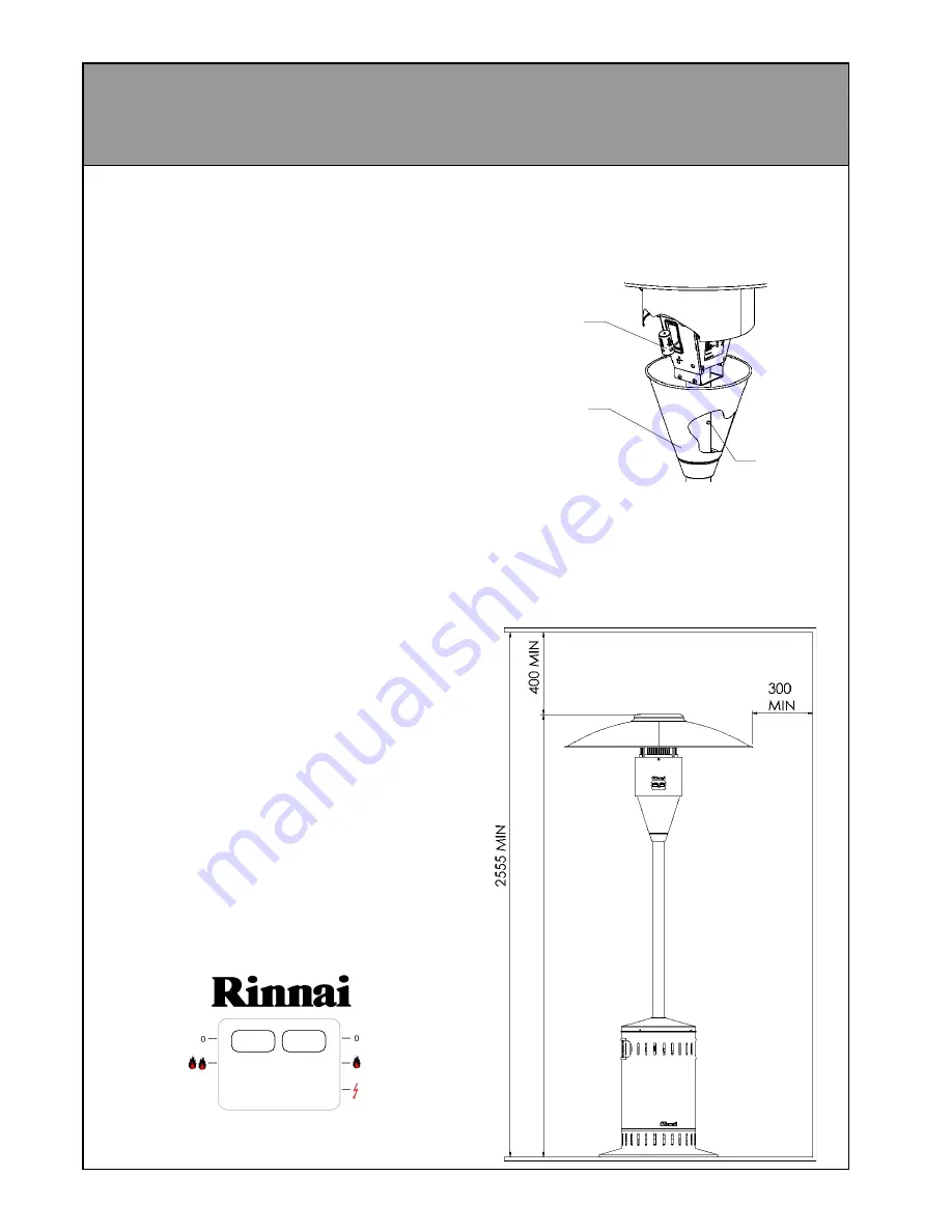
Press the release button on the back of the pole
and slide the battery cover down to allow access
to the battery. Replace using a C size battery
only.

Minimum clearances
This appliance must not be operated unless the
following distances are maintained between the
heater and any combustible material

Ensure that any curtains or shade cloths etc. are
secured and will not get near the heater.

Release
button

Battery
cover

Battery

Summary of Contents for PATIOSSL

Page 1: ...on CodeAG601 NZ 5261 Any other relevant statutory regulation For Outdoor Use Only LP Gas Only FEATURES Completely self contained High efficiency radiant plaques Stainless steel construction Battery ig...

Page 2: ...damage the gas hose when assembling the appliance and when fitting or removing the gas bottle and bottle cover In the event of damage being evident cracks tears abrasionetc thehosemust be replaced imm...

Page 3: ...the connection for leaks as described in the assembly instructions 5 Replace the bottle cover so that it is resting completely on the base taking care not to trap the gas supply hose against the legs...

Page 4: ...t the battery is properly installed and has a charge 6 When the main burner has ignited then hold the knob down for a further 15 seconds to maintain ignition 7 Once ignition has been established the s...

Page 5: ...REA Definition of an outdoor area The following diagrams show the definition of an outdoor area as described inAG405 This appliance must not be operated in a confined space that does not meet these re...

Page 6: ...6 OUTDOOR AREA CONTINUED...

Page 7: ...d leg flange have been bolted together for shipping purposes and will need to be separated before assembly can begin There is also a rubber edging strip around the lower rim of the burner tube This wi...

Page 8: ...crews as this may strip the threads 5 Slide the stainless steel bottle cover assembly over the pole then remove the protective rubber strip from the end of the burner assembly spigot tube Remove the b...

Page 9: ...embly under battery cover Gas supply hose Regulator Paint brush with soap solution 12 Attach the gas supply hose refer page 3 connecting gas bottle to the regulator and tighten using a spanner IMPORTA...

Page 10: ...rol Rinnai lever control combination Burner Radiant plaque Regulator POL 2 74 Kpa Test point pressure 2 55 kPa Gas type LPG Ignition Battery spark Battery 1 5 V c size Outer materials 304 Stainless st...

Reviews: