background image


Persons carrying out installation work on the Rinnai Infinity Hot Water Package require the following 
certificates  

For any gas work carried out:  Gas Safe Register Registration and ACS certification For installation of 
the Hot water system: proof of competence which can be shown through a Registered Operative 
Identity Card for the installation of Unvented Domestic Hot Water Systems or the Association of 
Installers of Unvented Hot Water Systems (Scotland and Northern Ireland.) For installation of electrical 
wiring:  EIC certification. IEE 16th Edition  

Building Regulation G3 draws attention to the Building Regulations 1991, especially 
Regulation 11(1), 12(4), and 13(3). The following is quoted from these and Building Regulation 
G3.  

A person who intends to carry out building work or to make a material change of use shall-- give to the 
local authority full plans and a building notice accompanied by a statement which specifies:  

a:  the name, make, model and type of hot water storage system to be installed  

b:  the name of the body, if any, which has approved or certified that the system is capable of 
performing in a way which satisfies the requirements of paragraph G3 of Schedule 1.*  

c:  the name of the body, if any, which has issued any current registered operative identity card to the 
installer or proposed installer of the system.  

The full plans shall consist of a description of the proposed building work or material change of use, 
and the plans, particulars and statements required.  

*In the Secretary of State’s view requirement G3 will be met if a hot water storage system that has a 
storage vessel with no vent pipe to the atmosphere:  

a: has been installed by a competent person  

b: has safety devices that prevent the temperature of the stored water at any time exceeding 
100°C;  

c: has pipework that safely conveys the discharge of hot water from safety devices to where it is visible 
but will cause no danger to persons, in or about the building.  

The Rinnai Infinity hot water storage system, like most systems over 150 litres capacity, has been 
supplied as a package with the necessary safety devices to prevent the temperature of the stored water 
from exceeding 100°C.  It is the responsibility of the installer to make sure that proper certification has 
been gained, and that the system is installed to the requirements of G3 and of this installation manual.  

Additionally the installation must be carried out to the requirements of Building 
Regulations issued by the Department of the Environment Building Standards 
(Scotland) Regulations.  

I.E.E. Wiring regulations for electrical installations. BS 6700  Local byelaws Water regulations Health 
and safety at work etc. Act 1974  

Such other specifications and regulations that may supersede or complement the above documents.  
Additional documents listed in the Infinity water heater manual.  
 

Disposal Information:  

Under the laws and local regulations, all items must be disposed separately from household waste. 
When this product reaches the end of useful life, it should be taken to a collection point identified by 
the local authorities. The recycling of the product at the time of disposal will help conserve natural 
resources and ensure that it is recycled in a manner that protects human health and environment. 

WARNINGS 

Summary of Contents for Infinity Series

Page 1: ...1 Infinity Storage Packs Installation Manual IMPORTANT Read these instructions carefully before attempting installation or use of this appliance All work must be carried out by competent persons ...

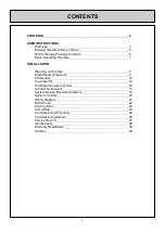
Page 2: ...ut the Site 8 Water Heater Pipework 9 Schematics 10 Unvented Kit 12 Hot Water Storage Cylinder 14 Cylinder Dimensions 15 System Design Recommendations 18 System Controls 20 Wiring Diagram 21 Extra Pump 22 Extra Cylinder 22 Pump Data 23 Commissioning Procedure 24 Commissioning Record 26 Service Record 27 UK Warranty 28 Warranty Registration 30 Contact 32 CONTENTS ...

Page 3: ...EATERS PLEASE READ ALL FOLLOWING INSTRUCTIONS FULLY FAILURE TO FOLLOW THESE INSTRUCTIONS AND PIPING SCHEMATICS IMPLICITLY COULD CAUSE SERIOUS INJURY AND DAMAGE TO PROPERTY ANY WARRANTY CLAIMS WILL BE NEGATED AND RINNAI UK WILL NOT BE HELD ACCOUNTABLE FOR ANY DAMAGE OR THIRD PARTY CLAIMS WARNINGS ...

Page 4: ...will be met if a hot water storage system that has a storage vessel with no vent pipe to the atmosphere a has been installed by a competent person b has safety devices that prevent the temperature of the stored water at any time exceeding 100 C c has pipework that safely conveys the discharge of hot water from safety devices to where it is visible but will cause no danger to persons in or about th...

Page 5: ...und in IP 14 03 from the BRE Preventing Hot Water Scalding In Bathrooms Using TMVs This list is not comprehensive The responsibilities relative to the Rinnai Infinity type of hot water system can be summarised in the following way Water temperatures in cylinders should always be over 600 C A secondary return must return at over 500 C The water at the furthest outlets must reach 500 C within 60 sec...

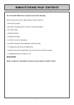
Page 6: ...Primary Pump 1 x Mains Valve Kit 1 x Expansion Vessel 1 x TSTAT1 Control Thermostat 1 x TSTAT2 Safety Thermostat High Limit Thermostat 1 x Temperature and Pressure Relief Valve 1 x MC91 Controller for diagnostics only not to be left connected to heater 1 x Installation Manual and Service Log Optional Extra Water Conditioner in Hard Water Areas recommendation in ACOP L8 2014 RINNAI STORAGE PACK CON...

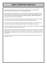
Page 7: ...nai Water Heater s will shut off It is normal for the burner on the Rinnai Water Heater s to modulate back to a low burner rate as the water temperature within the storage cylinder rises near to thermostat set temperature At times of no demand the primary pump will draw water out of the bottom of the cylinder to reheat it as and when required due to the heat loss of the vessel At times of heavy dr...

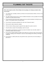
Page 8: ...ilable for the entire load of the water heaters 5 There must be water and electric available 6 The floor must be strong enough to support the full weight of the cylinder when full 7 There should be enough room and lighting to service the units 8 If the heaters are at high level or access is by means of a ladder there should be a ladder or scaffolding available onsite at all times 9 There must be s...

Page 9: ...an be used when the heaters are near as possible to the cylinder For heaters separated from the cylinder the size of the pipe work may have to be increased The pipe sizes given are for Primary pipe work including the cold water header from the primary pump to the last branch and the hot water header from the outlet of the first heater to the connection point on the cylinder 1 heater 16 l min 22 mm...

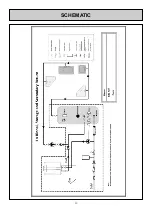
Page 10: ...10 SCHEMATIC ...

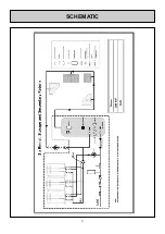
Page 11: ...11 SCHEMATIC ...

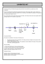
Page 12: ... The pipe work bore of the components The Pipe work bore is based on the maximum flow rate from taps at any one time The size of the Expansion vessel The expansion vessel is based on the size of the cylinder and volume of primary pipe work Pipe work Bore 1 inch for max flow rates up to around 50 litre minute 1 5 inch for max flow rates up to around 120 litre minute 2 inch for max flow rates up to ...

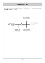
Page 13: ...13 The 1 inch Kit comes with a Caleffi Manifold Valve but all larger sizes have individual components The ports for the 1 inch kit are as follows UNVENTED KIT ...

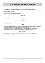
Page 14: ...200mm above Siting The cylinders must be sited indoors The unit is made to be floor mounted Whatever it is installed on must be capable of holding the weight of the cylin der when it is full The cylinders can be placed alongside a wall or in a corner as long as the connections are accessible If the cylinder is built in to a cupboard there should be room to remove it Pressure Rating The 300 and 500...

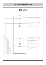
Page 15: ...15 300 Litre CYLINDER DIMENSIONS ...

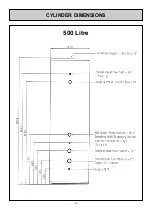
Page 16: ...16 500 Litre CYLINDER DIMENSIONS ...

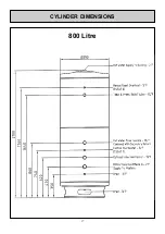
Page 17: ...17 800 Litre CYLINDER DIMENSIONS ...

Page 18: ...e check valve from the unvented kit and the cylinders Bi Directional pipework The expansion vessel and safety relief valve must have a direct uninterruptable path to the cylinder to guarantee the system has capacity for expansion this is a regulation to keep the system safe The hot water supply from the hot water storage cylinder comes out of the top and goes off to the outlets There must be an is...

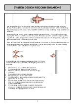
Page 19: ...rt for the 300 and 500 litre tanks In some installations this may require a reducing bush For the 800 litre tank the T P Valve must be tee d in to the hot water outlet from the top of the tank Full instructions on drainage are supplied with the T P Valve Additional information is available in Building Regulation G3 in summary 1 Do not reduce the size of the drain pipework 2 The pipework must have ...

Page 20: ... that the connection is closed when the system is operating safely and opens if it overheats If it opens the power to all heating inputs immersions included in to the cylinder will be lost and the reset button must be pressed to reset the Stat TSTAT2 TSTAT1 The temperature of the water in the cylinder is controlled by turning the primary pump on and off when the temperature in the cylinder is belo...

Page 21: ...21 WIRING DIAGRAM ...

Page 22: ...or fit in to the space where it s to be installed When two tanks are used they must be piped in a pyramid pipework layout The reverse return pipework method will not balance the systems because of the bidirectional pipework Two control thermostats TSTAT1 should be used The pump should not come on until BOTH thermostats are below the set point Two high limit stats TSTAT2 must be used and the system...

Page 23: ...23 PUMP DATA ...

Page 24: ...nufacturers specification 6 Make sure the drain is closed then open up the highest hot and cold water taps and other terminal fittings 7 Open the mains water isolation valve and allow the cylinder to fill 8 Once water is visibly coming out of the furthest out let close off the mains water and check the system for leaks 9 Manual test all pressure reliefs to ensure they operate and that the discharg...

Page 25: ...s and filters 2 Check the pressure of the expansion vessel and top up if required 3 Check the T P Valve opens and closes correctly 4 Check the safety relief valve opens and closes correctly 5 Check all discharge pipework is clear from obstruction 6 Check the water pressure after the pressure reducing valve 7 Check the temperature of TSTAT1 is set to between 60 and 65 C 8 Check the High limit stat ...

Page 26: ...26 COMMISSIONING RECORD ...

Page 27: ...27 SERVICE RECORD ...

Page 28: ...i will replace the product with a comparable product at Rinnai s discretion If a component or product returned to Rinnai is found to be free of defects in material or workmanship or damaged by improper installation the warranty claim may be denied HOW DO I GET SERVICE Contact your supplier or Rinnai UK Proof of date of purchase is required to obtain warranty service You can show proof of purchase ...

Page 29: ...rial processes Any application that uses Rinnai water heaters in conjunction with storage tanks Any application that uses Rinnai water heaters in conjunction with a flow return system Water heaters installed as components of centralised bulk hot water systems Situations defined as Commercial Use MUST have the Rinnai HDC range of water heaters to be eligible for the Commercial Use warranty Rinnai I...

Page 30: ...fully commissioned as per Rinnai Instructions Site Address Installing Engineer Signature Date Commissioning Engineer Signature Date Quantity of Heaters and Model Size of Vessel Please send a copy of this to RINNAI UK 9 Christleton Court Runcorn Cheshire WA7 1ST OR engineer rinnaiuk com WARRANTY REGISTER ...

Page 31: ...31 ...
Page 32: ...32 CONTACT UK LTD 9 Christleton Court Manor Park Runcorn Cheshire WA7 1ST Tel 01928 531870 Fax 01928 531880 E mail info rinnaiuk com Web www rinnaiuk com V4 24 08 15 PS ...

Reviews: