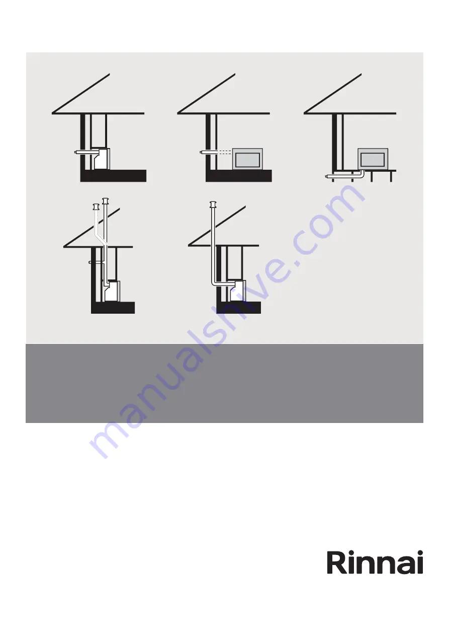
Arriva and Evolve gas fireplaces
Flue installation guide
Page 1: ...Arriva and Evolve gas fireplaces Flue installation guide...
Page 2: ...alled with an approved flue system approved components are shown in this guide Warning Improper installation adjustment alteration service and maintenance can cause property damage personal injury or...
Page 3: ...wall terminal 21 Connecting the heater exhaust pipe 22 Connecting the air supply 23 Arriva condensate drain kit connection 24 Evolve condensate drain kit connection 25 Appendices Appendix 1 ESBEND 90...
Page 4: ...direct flue kit available for the Evolve is the ASPDFK The direct mushroom flue kits that can be used for the Arriva are not suitable as the telescopic exhaust section of the Evolve is not long enoug...
Page 5: ...When considering the location of the fire ensure the flue path is free from obstructions such as noggins wiring joists etc Adaption flue kit Flue pipe ESPIPE900 Wall terminal ESWTERM Vertical in wall...
Page 6: ...te the o rings on the inner pipes prior to assembly This is important as o rings can dry out and break and replacing o rings is difficult Do not use petroleum based lubricants as these will cause dete...
Page 7: ...minal at all times DO NOT DO NOT DO NOT DO NOT Do not flue into natural draught flues or fireplaces Do not flue into other rooms Do not flue into roof spaces Do not flue under floor spaces To ensure p...
Page 8: ...the fire Direct flue kit ASPDFK aluminium Suitable for walls up to 385 mm thick can be cut to length Can also be used with ESPIPE900 for longer flueing The minimum length when measured from the back p...
Page 9: ...flue installations when used with the adaption flue kit Wall plate ESPLATE Used in down and out flueing to cover the floor penetration and also as an extra wall cover if required to tidy up an install...
Page 10: ...Socket o ring end of previous component Socket o ring end do not cut Non socket end can be cut Connecting the 45 bends ESBEND If installed incorrectly there is potential for the outer bend to overhea...
Page 11: ...ue transition When installed as a vertical flue the flue transition is fastened to the rear wall by the wall straps supplied Elbow component of the adaption kit requires 25 mm clearance to combustible...
Page 12: ...e markings are still useful for indicating the correct position of the flue transition within the enclosure for other flue applications For weatherboard walls drill through the centre of the weatherbo...
Page 13: ...le to pull the ties two or three slots past the starting point Cut the ties approx 20 mm past the lugs and bend so they are parallel with the wall 7 Attach ties Do not extend beyond red line Extension...
Page 14: ...penetration The minimum diameter is 80 mm to non combustible surfaces such as brick and 100 mm to combustible surfaces such as plaster Allow for a continuous 2 fall from the fire to the wall terminal...
Page 15: ...ed using the ESBEND kit 4 Create a vertical roof terminal 5 Secure joints between flue components through the outer pipes with screws and secure the entire flue system using the wall straps supplied 6...
Page 16: ...casting and the ESPIPE900 The transition component must not be connected directly to the ESPIPE900 which is plastic due to the heat of the flue gases 3 Fit lengths of ESPIPE900 as required Allow for a...
Page 17: ...to non combustible surfaces such as brick and 100 mm to combustible surfaces such as plaster Allow for a 2 fall back to the heater 2 Create the 90 bend using the ESBEND kit 3 Join the condensate trap...
Page 18: ...nterior wall Wall plate Stand off clip Interior wall Floor penetration 1 Flue slide stopper provided with the ASPKIT03 EVOKIT03 2 Air hose from unit 3 Condensate trap component acts as a transition pi...
Page 19: ...900 as required 4 Create the floor penetration ensure the hole edges are smooth The minimum diameter is 80 mm to non combustible surfaces such as brick and 100 mm to combustible surfaces such as plast...
Page 20: ...e 3 From the new end of the outer pipe measure and mark off an additional 12 mm on the inner pipe Cut the inner pipe at this mark Take care to keep the cut parallel to the outer pipe The additional 12...
Page 21: ...s shown below Take care to avoid cutting the external wall plate and keep the cuts of the internal and external pipes as parallel as possible Remove all burrs and swarf from the cut ends 3 Align the a...
Page 22: ...tor groove A red line will show if you have gone too far 3 Adjust the telescopic exhaust pipe to attain the desired position of the heater 4 Fix the telescopic exhaust pipe in place with the flue slid...
Page 23: ...is properly secured to the air connection on the flue system using the cable tie provided refer image on p 16 and that the rubber cap is in place on the unused air intake Flue pipe of the heater R2731...
Page 24: ...so ensure the path of the condensate drain hose is kept away from hot surfaces Failure to install the condensate kit correctly may cause damage to the heater and flue system 1 Insert the barbed end of...
Page 25: ...5 Evolve condensate drain kit connection Complete the gas air hose and flue connection If vertically flueing ensure the condensate tube provided with the EVOKIT03 flue kit is attached to the condensat...
Page 26: ...bend to overheat The spacers are mandatory and required for correct alignment of the flue components when bends are used When fitted correctly the inner and outer pipes of the ESBEND will be self cent...
Page 27: ...correctly there is potential for the outer bend to overheat The spacers are mandatory and required for correct alignment of the flue components when bends are used When fitted correctly the inner and...
Page 28: ...Tel 0800 746 624 http www youtube com rinnainz http facebook com rinnainz Rinnai co nz Arriva Evolve flue installation guide 10726 I...