11
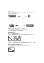
5.7 Video Output
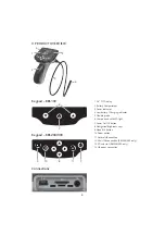
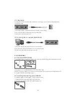
The inspection camera is equipped with a video output, so the image may be viewed on a larger display and
recorded if required
Connect video cable (B) between camera output (14) and AV input on display
Switch on camera and select video input channel on the display
Camera picture will then be displayed
5.8 Transferring files to a computer (RBS200/300)
Connect USB cable (C) between camera output (12) and computer
Switch on camera, computer will then detect unit as a removable disk
Files can now be copied over to computer as required
6. ACCESSORIES
6.1 Clip-on tools (RBS100/200)
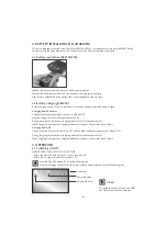
The inspection camera is supplied with a hook, mirror and magnet tool to aid inspection and component retrieval
Ensure the tool is securely clipped onto the camera head before using
WARNING: Do not use excessive force to insert or retrieve probe when using clip-on tools, no responsibility will
be accepted for tools disconnecting during use.
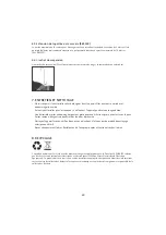
6.2 Connecting/Disconnecting camera (RBS300)
To replace or upgrade the camera probe, it can be easily be removed
First loosen the locking screw, then remove the flexible probe
Push the new camera into position and re-tighten locking screw

