Chapter 7: Antenna selection
60
RIM OEM Radio Modem for GSM/GPRS Wireless Networks
Antenna terminology
This section introduces some of the terminology that is used to describe antennas, and expands on
the summary of antenna requirements that are described below (refer to page 62).
Gain and ERP
Antennas produce gain by concentrating radiated energy in certain areas, and radiating less energy
in other directions. The amount of gain depends on the radiation pattern, antenna match, and
antenna efficiency. Antenna gain is given as a rating of the maximum increase in radiated field
energy density relative to a dipole antenna, expressed in decibels of power gain (dBd).
A dipole is a balanced antenna consisting of two radiators that are each a quarter-wavelength,
making a total of a half-wavelength. The widespread use of half-wave dipole antennas at very high
frequency (VHF) and ultra high frequency (UHF) has led to the use of a half-wave dipole as the
reference element.
At the antenna port, the output power of the RIM 1902G or RIM 1802G can be as high as 1W at
1900 MHz and 1800 MHz, 0.8W at 850 MHz, or 2W at900 MHz. The antenna gain (or loss) results in
an increase (or decrease) in this value. The actual output from the antenna is called the effective
radiated power (ERP). For example, if the radio modem delivers 2W of power to a 2.3 dBd gain
antenna, the ERP is 2.0
×
10^((2.3
÷ 10
) = 3.4W, the actual power radiated by the antenna in the
direction of maximum gain and polarization.
Impedance matching, return loss, and VSWR
The antenna, cables, and connectors in a radio frequency system must all possess the same
impedance. The impedance required by the RIM 1902G or RIM 1802G is 50 ohm, which is a widely
available industry standard. Any deviation from this value might result in impedance mismatch
and signal loss.
Impedance mismatch can also be caused by cable connections, cable lengths, and imperfections in
the cables and connectors. The mismatch causes some of the radio frequency energy to be reflected
from the mismatch location. This reflection interferes with the signal and reduces its amplitude,
which results in power loss.
Antenna mismatch can be expressed as a return loss (RL), which is the ratio of reflected power to the
incident power, expressed in decibels.
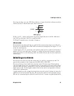
Return Loss equation
RL
=
×
10
10
log
P
P
reflected
output
Summary of Contents for 1802G
Page 10: ...10 RIM OEM Radio Modem for GSM GPRS Wireless Networks ...
Page 12: ...About this guide 12 RIM OEM Radio Modem for GSM GPRS Wireless Networks ...
Page 24: ...Chapter 2 Getting started 24 RIM OEM Radio Modem for GSM GPRS Wireless Networks ...
Page 75: ......
Page 76: ... 2002 Research In Motion Limited Published in Canada ...


