background image


PT2E-1747 


Combustible Gas Detector Head 

GD-D58

AC 

GD-D58

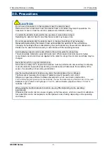
DC 

(TYPE GP) 

(TYPE NC) 


Operating Manual 


Summary of Contents for GD-D58-AC

Page 1: ...PT2E 1747 Combustible Gas Detector Head GD D58 AC GD D58 DC TYPE GP TYPE NC Operating Manual ...

Page 2: ...ontact output of the detector head must be used for an external alarm lamp buzzer while the alarm signal output must be used for an indicator or external recorder If these outputs are used to control other units we shall not be responsible for any malfunctions 4 The gas sensing part of the gas sensor installed in this detector head is made of metal porous sintered alloy permeated with an oxidation...

Page 3: ...for installation points 19 4 3 Precautions for system designing 20 4 4 How to install 22 4 5 How to wire 24 4 6 How to tube 32 5 How to Operate 33 5 1 Preparation for start up 33 5 2 Basic operating procedures 33 5 3 How to start the detector head 34 5 4 How to detect 35 5 5 How to exit 35 6 Alarm Activation 36 7 Maintenance 37 7 1 Maintenance intervals and items 37 7 2 Parts replacement 39 8 Stor...

Page 4: ...nd outputs voltages according to gas concentrations The indicator alarm unit both indicates a gas concentration and if a preset concentration level is exceeded triggers an alarm The detector head is a safety unit not an analyzer or densitometer which performs quantitative qualitative analysis measurement for gases Please fully understand the features of the detector head before using it so that it...

Page 5: ...osion proof certificate Please confirm the detector specification before using Please refer Declaration of Conformity that is at the end of this manual if you have CE marking type You can confirm instrument specification to see name plate as follows ATEX CE marking type name plate TIIS type name plate DC power specification only AC DC power specification ITRI type name plate AC DC power specificat...

Page 6: ...es liquid or vapor It may cause the color and shape of the window plate to be changed The flameproof joints are not intended to be repaired Do not open the lid when applying current The lid may be opened after five minutes or more after power off Do not attempt to repair the detector head by the user For the lid use hexagon socket head bolts specified by RIKEN KEIKI The drive lid must be closed du...

Page 7: ... it to a protective grounding circuit Zero adjustment in the atmosphere When the zero adjustment is performed in the atmosphere check the atmosphere for freshness before beginning the adjustment If other gases exist the adjustment cannot be performed properly thus leading to dangers when the gas leaks Do not use the low flow rate alarm function under the presence of silicon Silicon may accumulate ...

Page 8: ...nts liquid or highly concentrated vapor and others are applied to the plate for a long time its color and shape may be changed Never fail to perform a regular maintenance Since this is a safety unit a regular maintenance must be performed to ensure safety Continuing to use the detector head without performing a maintenance will deteriorate the sensitivity of the sensor thus resulting in inaccurate...

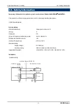
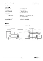
Page 9: ...a Protection Method Flameproof enclosure d Group II Category 2G Type of Protection and Marking code Ex db ⅡB H2 T4 Equipment Protection Level Gb Ambient Temperature 20 C to 53 C Electrical Data Supply voltage 24 Vdc Typ Electrical rating DC3 0V 430mA or DC5 0V 200mA Applicable Standard EN 60079 0 2012 A11 2013 EN 60079 1 2014 Installation GD D58 DC Hazardous Location Zone 1 Nonhazardous Location G...

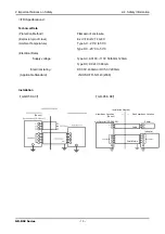
Page 10: ...re Type AC 20 C to 50 C Type DC 20 C to 53 C Electrical Data Supply voltage Type AC AC100 110V 50 60Hz 120mA Type DC DC24V 360mA Electrical rating DC3 0V 430mA or DC5 0V 200mA Applicable Standard JNIOSH TR NO 43 2008 Installation GD D58 AC GD D58 DC Hazardous Location Zone 1 Nonhazardous Location GasDetector GD D58 DC InstallationDiagram GD D58 DC Cable Indicator sensor Power ShieldCable sensor Zo...

Page 11: ...Type AC 20 C to 50 C Type DC 20 C to 53 C Electrical Data Supply voltage Type AC AC100 110V 50 60Hz 120mA Type DC DC24V 360mA Electrical rating DC3 0V 430mA or DC5 0V 200mA Applicable Standard JNIOSH TR NO 43 2008 Installation GD D58 AC GD D58 DC Hazardous Location Zone 1 Nonhazardous Location GasDetector GD D58 DC InstallationDiagram GD D58 DC Cable Indicator sensor Power ShieldCable sensor Zone ...

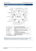
Page 12: ...unit and standard accessories GD D58 Series 12 3 Product Components 3 1 Main unit and standard accessories Main Unit including cable glands Unit mm Gas inlet Gas outlet Display 4 φ7 for M6 Cable connecting port Cable connecting port ...

Page 13: ...e number of wrenches as with the test certificates will be provided Dust removal filter with flow monitor 1 filter NOTE The dedicated control key is for maintenance It is not used for detection mode Keep it handy for use CAUTION Use the supplied dedicated control key to operate the detector head If products other than these accessories are used key operations cannot be accepted properly The contro...

Page 14: ...hange a value DOWN 5 Power lamp Power lamp Detection mode It lights up in green Maintenance mode It blinks in green 6 Fault lamp Fault lamp It lights up in yellow when an abnormality is detected in the detector head 7 Status display Displays the operating status This is not typically used by the user NOTE The nameplate on the front side of the detector head shows the precautions to be taken for ex...

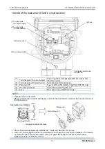
Page 15: ...cuit lid Remove the electric circuit lid and display unit to find behind them the electric circuit section shown in the figure above Power input terminal plates are GD D58 AC 3 pole and GD D58 DC 2 pole A fter use closely tighten the lid until the thread is no longer seen clockwise 8 rotations 1 4 rotation or more and the TOP marking faces upward Tighten the hexagon socket set screw with a tighten...

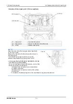
Page 16: ...e section shown in the figure above The bolt with the hexagon socket must use the stainless steel material of property class A2 70 Grease specified by RIKEN KEIKI BARRIERTA JFE 552 manufactured by NOK KLUBER If you can not prepare the specified grease use one that meets the following requirements 1 Material does not harden due to deterioration 2 Volatile solvent free 3 Material does not cause corr...

Page 17: ...es 3 3 Block diagram Electric Diagram GD D58 AC Gas sensor Controller CPU POWER OUTPUT 24 VDC AC DC converter Display POWER FAULT Seven segment LED four digit Magnetic operation part MENU ESC SET Flow sensor POWER INPUT 100 110 VAC Power supply part Pump ...

Page 18: ...3 Block diagram GD D58 Series 18 Electric Diagram GD D58 DC Gas sensor Controller CPU Display POWER FAULT Seven segment LED four digit Magnetic operation part MENU ESC SET Flow sensor POWER INPUT 24 VDC Power supply part Pump ...

Page 19: ...ge suddenly ATEX Specifications GD D58 DC 20 53 ITRI Specifications GD D58 AC 20 50 GD D58 DC 20 53 TIIS Specifications GD D58 AC 20 50 GD D58 DC 20 53 Do not install the detector head in a place exposed to direct sunlight or sudden changes in the temperature When selecting installation points avoid a place where it is exposed to direct sunlight or radiant heat infrared rays emitted from a high te...

Page 20: ...other gases exist around it 4 3 Precautions for system designing Using a stable power supply The external output and alarm contact of the detector head may be activated when the power is turned on when momentary blackout occurs or while the system is being stabilized In such cases use a UPS uninterrupted power supply or take appropriate actions on the receiving side of output signals The detector ...

Page 21: ...by lightning is impossible the following protective measures can be taken Protection against lightning Take appropriate measures in accordance with the importance of the facilities and the environment Provide protection by a lightning arrester cable arrester Although inductive lightning surge can be transmitted through the cable it is prevented by installing a lightning arrester before the field d...

Page 22: ...ctor head Attach the detector head on the wall and others using four M6 screws Tighten the hexagon socket head cap bolt fixing the lid and the main body with a tightening torque of 215 6 24 5N cm When closing the lid of the detector make sure that there is no dust on screw surfaces of the main body and lid Then apply grease as specified by RIKEN KEIKI 220 1000 Unit mm Lid turning jig ...

Page 23: ...e removed to perform maintenance or where the detector head cannot be removed because tubes or racks prevent access to it Do not install the detector head in a place where maintenance involves dangers for example near a high voltage cable CAUTION Grease specified by RIKEN KEIKI BARRIERTA JFE 552 manufactured by NOK KLUBER If you can not prepare the specified grease use one that meets the following...

Page 24: ...5 14 5 14 5 17 14 8 14 5 15 5 15 5 17 15 8 15 5 16 0 16 5 17 16 2 No cable Plug WARNING When installing the electric circuit lid do not let any foreign substance such as metal get into the terminal box This can cause a failure of the device or loss of explosion proof performance The lead in wire to the detector head must be installed in a way not to damage the explosion proof performance of the de...

Page 25: ... 11 14 11 8 11 0 allowable range 11 0 11 5 12 14 12 8 11 5 allowable range 11 5 12 0 12 14 12 8 12 0 allowable range 12 0 12 5 12 5 14 12 8 13 0 allowable range 13 0 13 5 13 5 14 13 8 16 0 allowable range 16 0 16 2 16 5 17 16 2 No cable Plug NOTE The following table shows an example of the outer diameters of the cables Use them for reference The outer diameters must be checked because they somewha...

Page 26: ...closely tighten the lid until the thread is no longer seen clockwise 8 rotations 1 4 rotation or more and the TOP marking faces upward Tighten the hexagon socket set screw with a tightening torque of 107 8 12 7 N cm The figure above shows GD D58 AC 3 4 5 6 1 2 3 4 5 6 AC L AC N FG Detector head signal Pump power supply 100 110 VAC input TN2 TN1 3 4 5 6 1 2 3 4 5 6 5 Detector head signal Pump power...

Page 27: ...lamping of the wire due to a shorter bare wire length may cause defective electric conduction or heating Catching the wire insulation due to a shorter bare wire length may cause defective electric conduction or heating Exposing the wire due to a longer bare wire length may cause defective insulation or a short circuit Be careful not to break up the wire If the wire is broken up when inserted to th...

Page 28: ...her the wire is connected securely pull the wire gently Do not pull the wire strongly Push the lever with your finger to lower the spring in its inside While holding down the lever insert the wire into the round wiring hole until it reaches the deepest point Once the lever is released the wire is secured ...

Page 29: ...low attach the parts in the following order cable gland eccentric washer washer and rubber seal to the cable then connect the cable into the main unit then screw the cable gland to tighten the rubber seal When installing the cable gland wipe the cable gland mounting part the hexagon soket set screw the grounding screw and the cable gland and wipe the specified grease How to insert a plug into a ca...

Page 30: ... NOK KLUBER If you can not prepare the specified grease use one that meets the following requirements 1 Material does not harden due to deterioration 2 Volatile solvent free 3 Material does not cause corrosion at the surface 4 Silicon free 5 Validation of suitability depends on the specifications of grease manufacturer ...

Page 31: ...ead signal 3 5 6 1 GD D58 AC 13 2 4 14 TN2 TN1 11 12 GP 5001 5000 SR etc WARNING Before turning on the detector head do not forget to connect it to a grounding terminal For stable operation of the detector head and safety it must be connected to a grounding terminal Do not connect the grounding wire to a gas pipe The grounding must be made as D type grounding below 100 Ω of grounding resistance Fo...

Page 32: ...c1 8 thread inside of the sampling inlet outlet GAS IN GAS OUT to which BS unions are attached as standard Because their material varies depending on the gas to be detected please specify the material The compatible tube is a copper tube of Φ8 OD Φ6 ID The tube must be installed with the supplied sleeves attached to prevent a leak When the tube is cut its cut point may have a smaller inner diamete...

Page 33: ...ector head is connected to a grounding circuit Check that the wiring is connected to external device properly Check that the tubes are installed properly Check that the power supply voltage is compliant with the power supply specification and does not exceed the rating 5 2 Basic operating procedures Normally the detection mode is activated after the power is turned on Detection Mode The detector h...

Page 34: ...rocedures approximately 25 seconds for system check of the detector head and alarm deactivation Power on Initial clear approximately 25 seconds Detection mode The gas detection is not yet started just after the detector head is started up Turn ON the power switch of the indicator alarm unit according to 5 4 How to detect Power on Initial clear Detection mode CAUTION Do not turn off the detector he...

Page 35: ...rcuit lid Turn OFF the power switch of the detector head Close the electric circuit lid Only GD D58 AC has a power switch Since GD D58 DC does not have any power switch there is no need to open or close the electric circuit lid CAUTION If a new sensor is installed or the sensor is replaced even after the start up the sensor must be warmed up for a specified period which is determined depending on ...

Page 36: ...y malfunctioning contact RIKEN KEIKI immediately Low Flow Rate Abnormal Operations This alarm is triggered when the output value of the low flow sensor drops below the alarm setpoint The alarm is auto reset when the flow rate exceeds a certain level NOTE A low flow rate abnormality can be a cause of fault alarm For information on malfunctions error messages see 9 Troubleshooting When a fault alarm...

Page 37: ...a safety unit Maintenance item Maintenance content Daily maintenance Monthly maintenance Regular maintenance Power lamp check Check that the power lamp lights up Status display check Check that the status display is run and that the fault lamp is off Flow rate check Check that the float of the dust removal filter with flow monitor is visible Gas concentration display Check that the gas to be detec...

Page 38: ...low rate by using an external flow meter to check for abnormalities Filter check Checks the dust filter for dust or clogging Replaces a dirty or clogged dust filter Alarm test Inspects the alarm circuit by using the alarm test function Checks the alarm lamps Checks activation Checks the external alarm Checks the activation of the external alarm such as a buzzer Span adjustment Performs the span ad...

Page 39: ...intervals year Quantity pieces unit Remarks AC DC converter 6 months 3 6 years 1 Flow sensor 6 months 2 years 1 Tubes 6 months 3 8 years 1 Pump unit 6 months 1 2 years 1 Chamber assembly 6 months 3 8 years 1 Sensor cap assembly 6 months 3 8 years 1 After the part is replaced the operation must be checked by a qualified service engineer For the stable operation of the detector and safety ask a qual...

Page 40: ... to relocate the detector head or use it again When the detector head is relocated select a new place in accordance with 4 2 Precautions for installation points and 4 4 How to install For information on wiring see 4 5 How to wire The unpowered time must be minimized when the detector head is relocated 8 3 Disposal of products When the detector head is disposed of it must be treated properly as an ...

Page 41: ...ities momentary blackout of power supply system Provide the rated voltage Take measures such as checking or adding the UPS power supply line filter and insulation transformer Cable abnormalities open circuit not connected short circuit Check the wiring of detector head and related devices around it Abnormal operations Disturbances by sudden surge noise etc Turn off and restart the detector head If...

Page 42: ...leak and no other abnormalities at the detection point Presence of interference gas Disturbances by interference gases such as solvents cannot be eliminated completely For information on actions such as removal of filter please contact RIKEN KEIKI Disturbance by noise Turn off and restart the detector head If such a symptom is observed frequently take appropriate measures to eliminate the noise Su...

Page 43: ... or 2 0mm2 2 core Power cable laying distance Less than 375m in case of CVV 1 25mm2 Less than 550m in case of CVV 2 0mm2 Transmission cable CVVS etc 1 25mm2 or 2 0mm2 4 core or 6 core in common with power cable Power supply 24 VDC 10 Power consumption Maximum 8 6 W Cable connecting port Pressure proof packing gland G3 4 Compatible cables φ 9 0 φ 16 0mm in outer diameter Tube connecting port Rc1 8 ...

Page 44: ...e Less than 1 25km in case of CVV 1 25mm2 Less than 2 0km in case of CVV 2 0mm2 Transmission cable CVVS etc 1 25mm2 or 2 0mm2 4 core or 6 core in common with power cable Power supply 100 110 VAC 10 50 60 Hz Power consumption Maximum 13 VA Cable connecting port Pressure proof packing gland G3 4 Compatible cables φ9 0 φ13 0 16 0mm in outer diameter Tube connecting port Rc1 8 O D 8 1t half union for ...

Page 45: ...le laying distance Less than 375m in case of CVV 1 25mm2 Less than 550m in case of CVV 2 0mm2 Transmission cable CVVS etc 1 25mm2 or 2 0mm2 4 core or 6 core in common with power cable Power supply 24 VDC 10 Power consumption Maximum 8 6 W Cable connecting port Pressure proof packing gland G3 4 Compatible cables φ9 0 φ13 0 16 0mm in outer diameter Tube connecting port Rc1 8 O D 8 1t half union for ...

Page 46: ...re or 3 core Power cable laying distance Less than 1 25km in case of CVV 1 25mm2 Less than 2 0km in case of CVV 2 0mm2 Transmission cable CVVS etc 1 25mm2 or 2 0mm2 4 core or 6 core in common with power cable Power supply 100 110 VAC 10 50 60 Hz Power consumption Maximum 13 VA Cable connecting port Pressure proof packing gland G3 4 Compatible cables φ9 0mm in outer diameter Tube connecting port Rc...

Page 47: ...wer cable laying distance Less than 375m in case of CVV 1 25mm2 Less than 550m in case of CVV 2 0mm2 Transmission cable CVVS etc 1 25mm2 or 2 0mm2 4 core or 6 core in common with power cable Power supply 24 VDC 10 Power consumption Maximum 8 6 W Cable connecting port Pressure proof packing gland G3 4 Compatible cables φ9 0mm in outer diameter Tube connecting port Rc1 8 O D 8 1t half union for Cu t...

Page 48: ...ent with a mixture of gas inert alumina and glass sintered on it When a combustible gas comes into contact with the surface of the detecting element with new ceramic oxidation catalyst sintered on it the gas burns causing the temperature to rise In accordance with this temperature change there occurs a change in the resistance of a heat resistant alloy wire coil that constitutes the element These ...

Page 49: ...wn air or gas comes into contact with the heated detecting element the detecting element temperature changes due to the heat dissipation and the electrical resistance of the element changes according to the temperature changes Since the resistance changes are in proportion to the gas flow rates the Wheatstone bridge circuit can identify the changes as the flow rate D Detecting element C Compensati...

Page 50: ...e for details Initial clear Output from the detector head fluctuates for a while after turning on the power This is a function to prevent triggering alarm during that time Full scale Maximum value of the detection range LEL A unit which the lower explosive limit LEL of the combustible gas to be detected is set to 100 ppm A concentration unit that means part per million of the combustible gas to be...

Page 51: ...GD D58 Series 51 ...

Reviews: