background image

RIGOL 

© 2008 RIGOL Technologies, Inc. 

  User’s Guide for VS5000 Series 

1-17 


To Understand the Horizontal System   

 
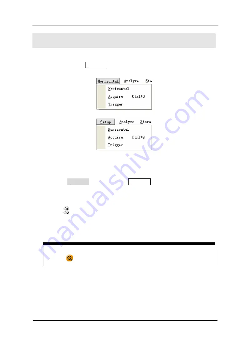
Figure 1-14 shows the Horizontal menu, which leads the setting of the horizontal 
parameters. 


Figure 1-15 

 Horizontal Menu 

1


Using the Horizontal function in the Horizontal menu to set the waveform 
horizontal options. In the 

Horizontal

 window, set the waveform display format 

(Y-T, X-Y and Roll) and horizontal 

Scale

 and 

Offset

Click the 

  button, changes the sweep speed in a 1-2-5 step sequence and the 

value is displayed in the status bar. The time base ranges of the VS5000 series 
are listed as follows. The horizontal scan speed is from 5ns/div

[1]


to 50s/div. 


Delayed Scan Shortcut key 

Click the 

  button to enter Delayed Scan mode. 

[1]


NOTE: 

The speed of horizontal scan varies in different models. 


2


Click the 

Offset

 function in the 

Horizontal

  window  to  adjust  the  horizontal 

offset. 

Summary of Contents for VS5000 Series

Page 1: ...User s Guide RIGOL Publication Number UGA05109 1110 Oct 2008 VS5000 Series Digital Oscilloscope 2008 RIGOL Technologies Inc All Rights Reserved...

Page 2: ......

Page 3: ...s are protected by patent laws in and outside of the P R China z Information in this publication replaces all previous corresponding material z RIGOL reserves the right to modify or change part of or...

Page 4: ...iguration are as follows Hardware Configuration z Upwards of 1G processor z 200M hardware space z 800x600 display resolution z 256RAM z USB Operating System Microsoft Windows 2000 2003 XP Recommended...

Page 5: ...rminals of the instrument Connect The Probe The probes ground terminals are at the same voltage level of the instrument ground Do not connect the ground terminals to a high voltage Observe All Termina...

Page 6: ...or VS5000 Series IV Do not operate in an Explosive Atmosphere Keep Product Surfaces Clean and Dry The disturbance test of all the models meet the limit values of A in the standard of EN 61326 1997 A1...

Page 7: ...resses are variable for that reason the transient withstand capability of the equipment is made known to the user WARNING IEC Measurement Category I The HI and LO input terminals may be connected to c...

Page 8: ...result in damage to this product or other property Terms on the Product These terms may appear on the product DANGER indicates an injury hazard may be immediately accessible WARNING indicates an inju...

Page 9: ...eal time sample rate and 25 GSa s maximum equivalent sample rate z A true Mixed Signal Oscilloscope with 16 channels Logic Analyzer for some models z Memory depth 1M points Single Channel 512k points...

Page 10: ...nderstand the functions and measurements of instrument deeply z Chapter 3 Application Examples To show the measurement functions directly by application examples z Chapter 4 Troubleshooting Provide yo...

Page 11: ...2 Operating Your Oscilloscope 2 1 To Set the Vertical system 2 2 To Set the Horizontal System 2 26 To Set the Trigger System 2 33 To Set the Sampling System 2 48 To Save Load and Print Setup 2 53 To S...

Page 12: ...User s Guide for VS5000 Series X Chapter 4 Troubleshooting 4 1 Chapter 5 Specifications 5 1 Chapter 6 Appendix 6 1 Appendix A Accessories 6 1 Appendix B Warranty 6 2 Appendix C Maintenance 6 3 Appendi...

Page 13: ...z Front and Rear Panels At a Glance z Software Setting and Equipment Connecting z To Understand the User Interface z To perform a functional check z To compensate probes z How to use digital probes V...

Page 14: ...ssories supplied with the instrument are listed in Accessories in this guide If the contents are incomplete or damaged please notify the RIGOL Sales Representative 3 Inspect the instrument In case the...

Page 15: ...onnectors graphical representations interfaces and how to use them Read the chapter carefully before further operations Figure 1 1 Front panel of VS5000 Series Oscilloscope Figure 1 2 Rear panel of VS...

Page 16: ...you get a new RIGOL VS5000 Oscilloscope For more details please refer to the following text Software Setting Please insert and drive the disk accessory of the RIGOL VS5000 oscilloscope Then double cli...

Page 17: ...nually 1 Obtain an IP automatically Please set network according to the following steps z Connecting On condition that the USB cable was being connected you can configure l Property of Network protoco...

Page 18: ...in Network Communications z Select Network Communication Open Control Connection menu it will pop up a dialog click check option LAN and select Network Communication then set IP address and port valu...

Page 19: ...de for VS5000 Series 1 7 To Understand the User s Interface Click the VS5000 software icon after you finished the software setting and equipment connecting Then a user interface will be popped up as f...

Page 20: ...2008 RIGOL Technologies Inc User s Guide for VS5000 Series 1 8 Figure 1 4 Display Interface Analog and Digital channels Channel 1 Channel 2 Digital Channels Trigger level Trigger point Time reference...

Page 21: ...1 5 Instruction of the Front Panel 2 Input a signal to a channel of the oscilloscope VS5000 Series are equipped with dual channels plus external trigger and 16 channels logic analyzer only for VS5000...

Page 22: ...he probe attenuation Now select the 1 10 option Figure 1 7 Figure1 8 To Set the Probe To Set the Probe Attenuation 3 Attach the tip of probe and ground nip to the Connector of Probe compensator Click...

Page 23: ...roper connection Attach the probe tip to the Probe Compensator and the reference lead to the ground connector select CH 1 and then press the button 2 Check the shape of the displayed waveform Over com...

Page 24: ...applied to the leads at this step the oscilloscope may remain on 2 Connect one end of the flex cable FC1868 to the Logic Analyzer Input connect the other end to Logic Head LH1116 It is unnecessary to...

Page 25: ...ect a test clip to one lead wire make sure it is connected well Figure 1 11 Connect the Test Clip 4 Test the device with the clip Figure 1 12 Testing Instruction 5 Remember to connect Ground Channel t...

Page 26: ...l Press the button the oscilloscope automatically sets up VERTICAL HORIZINTAL and TRIGGER controls to display the input signal Adjust the controls manually to get the best results if necessary Connect...

Page 27: ...is displayed for a short time indicating how far the ground reference is located from the center of the screen Use the left mouse button to dragging the CH1 symbol and or use the Scale and Offset opti...

Page 28: ...k to 0 2 Change the vertical setup and notice that each change affects the status bar differently Left click the vertical status and use the number keyboard to input the exact Scale value volt div and...

Page 29: ...window set the waveform display format Y T X Y and Roll and horizontal Scale and Offset Click the button changes the sweep speed in a 1 2 5 step sequence and the value is displayed in the status bar...

Page 30: ...e middle circular button to set the horizontal offset to 0 as a shortcut key 3 In the Format window of the Horizontal functions window select the display mode to Y T X Y or Roll Horizontal position co...

Page 31: ...he Horizontal menu The following exercise guides through the buttons and settings Figure 1 16 Trigger Control 1 To set the trigger function in the Trigger menu Drag the Trigger level to adjust the tri...

Page 32: ...ton to start an acquisition regardless of an adequate trigger signal usually used in Normal or Single trigger mode If the acquisition is already stopped click this button to start the acquisition agai...

Page 33: ...recommended to perform all of the following exercises to get the most of the powerful measurement capabilities of the oscilloscope Understand the vertical system 1 Vertical Understand the horizontal...

Page 34: ...nel Window Turn the function On Off In front of the function option there is a or choice box means this function is turned OFF means it is turned ON CAUTION 1 To aviod damaging the input part of the o...

Page 35: ...the Input Impedance to be 50 ohm BW Limit ON OFF Limit the channel bandwidth to 20MHz to reduce display noise Get full bandwidth Probe 1 1 1 10 1 100 1 1000 Set this to match the probe attenuation fac...

Page 36: ...the Analog function in the Vertical menu and enter the Channel window Set the Coupling to AC In this setting it blocks the DC component of the input signal Figure 2 2 AC Coupling Setting Right click t...

Page 37: ...RIGOL 2008 RIGOL Technologies Inc User s Guide for VS5000 Series 2 5 Figure 2 3 DC Coupling Setting DC Coupling...

Page 38: ...utton the Channel window will appear Turn the BW Limit function off The oscilloscope is set to full bandwidth and will pass the high frequency component in the signal Figure 2 4 Close the BW Limit Rig...

Page 39: ...ge or check the probe attenuation setting press the CH1 or CH2 button according to which channel are in using toggle the Probe soft button to match the attenuation factor of the probe This setting rem...

Page 40: ...setting the Vertical Sensitivity in the form of 1 2 5 that is 2mV div 5mV div 10mV div 20mV div 10 V div Fine This setting changes the vertical scale with accurate value Figure 2 7 Scale and Offset Wi...

Page 41: ...displayed waveform 180 degrees with respect to the ground level When the oscilloscope is triggered on the inverted signal the trigger is also inverted Figure 2 8 and 2 9 show the changes before after...

Page 42: ...enu or right click the button to show the Logic Analyzer window Figure 2 10 Logic Analyzer Interface Table 2 3 Logic Analyzer Settings Function Setting Description D7 D0 Set up channel group D7 D0 D15...

Page 43: ...ow to set the Channel ON OFF Wave Size Threshold Type and Reset the waveform display position 2 Drag the digital channel sign to move the digital waveform to the designated location 3 Click the Reset...

Page 44: ...nc User s Guide for VS5000 Series 2 12 Figure 2 12 To Set the Threshold Type Threshold explanation LOGIC STANDARD THRESHOULD VOLTAGE TTL 1 4V CMOS 2 5V ECL 1 3V USER 8V to 8V Setup the value of thresh...

Page 45: ...ic functions include add subtract multiply and FFT for Channel 1 and Channel 2 The mathematic result can be measured by the grid and the cursor The Math function may turn on four channels each channel...

Page 46: ...on Math On Off Turn this math channel on Turn this math channel off Operation A B A B A B FFT Filter Add source A and source B Subtract source B from source A Multiply source A by source B Fast Fourie...

Page 47: ...2 14 Digital Filter Interface Table 2 5 Digital Filter Function Function Setting Description Source CH1 CH2 Define CH1 or CH2 as source Digital Filter Off On Turn off the digital filter Turn on the di...

Page 48: ...tion use the addition subtraction and multiplication function to operate and analyze the waveform Figure 2 15 The Addition Subtraction and Multiplication Function Enter the Math window Select the math...

Page 49: ...r supplies z Analyzing vibration Table 2 6 FFT Function Function Setting Description FFT OFF ON Turn off the FFT Open the FFT Operation A B A B A B FFT Add source A and source B Subtract source B from...

Page 50: ...ponent magnitude values To minimize the DC component choose AC Coupling on the source signal 2 To reduce random noise and aliases components in repetitive or single shot events set the oscilloscope ac...

Page 51: ...ne waves with fixed frequencies Broadband random noise with a relatively slow varying spectrum Hanning Hamming Better frequency poorer magnitude accuracy than Rectangular Hamming has slightly better f...

Page 52: ...mory Click the Reference button in the Vertical menu go to the Reference window Figure 2 16 Reference Interface Table 2 8 Reference Function Display OFF ON Close waveform reference Open waveform refer...

Page 53: ...f Turn the file selection on Vertical Setting Verticaldisplacement Vertical scale Verticaldisplacementsetting Vertical scalesetting Horizontal Setting Horizontal displacement Horizontal scale Horizont...

Page 54: ...ton in the Reference window Figure 2 17 Open a Reference File Table 2 9 Export Function Function Setting Description Driver Select the driver location Switch the driver Open Load the file that was sel...

Page 55: ...button in the Reference window Figure 2 18 Save a Reference File Table 2 10 Import Function Function Setting Description Driver Select the driver location Switch the driver Save Save the file that was...

Page 56: ...t CH1 CH2 MATH1 MATH2 MATH3 and MATH4 channel 3 Adjust the Scale and Offset of the Vertical and Horizontal 4 Click the Save button to save the waveform being displayed on the screen as Reference NOTE...

Page 57: ...Logic Analyzer window to turn the channel off Table 2 11 Turn On Off channels Channel Mode Settings Status Indicator Channel 1 CH1 ON OFF CH1 yellow background CH1 gray background Channel 2 CH2 ON OFF...

Page 58: ...he horizontal scale causes the waveform to expand or contract with respect to the screen center Horizontal position changes the displayed waveform position relative to the trigger point Scale Set the...

Page 59: ...lative relation between vertical voltage and horizontal time X Y Show CH1 value at X axis CH2 value at Y axis Time Base Roll In Roll Mode the waveform display updates from right to left Scale Set the...

Page 60: ...ontal Setting Interface Marks The current waveform position window in the memory The trigger position in the memory The trigger position in the current waveform windows The horizontal time base the ma...

Page 61: ...is available during Roll Mode and it s only available when set to 500 ms div or slower Slow Scan Mode This mode is available when the horizontal time base is set to 50ms or slower In this mode the os...

Page 62: ...setting Figure 2 21 Delayed Scan The following describes the Delayed Scan display The screen is divided into two parts The upper half displays the main waveform window and the lower half displays an e...

Page 63: ...00 Series 2 31 Delayed Scan The symbol at bottom of the screen means the main time base and the symbol on the center bottom means the Delayed Scan time Delayed Scan shortcut key Delayed Scan function...

Page 64: ...d Channel 2 in the vertical axis Y The oscilloscope uses a none trigger acquisition mode data is displayed as dots Figure 2 22 The X Y Display The following modes or functions will not work in X Y mod...

Page 65: ...t of the trigger point The oscilloscope continues to acquire data while waiting for the trigger condition to occur After it detects a trigger the oscilloscope continues to acquire enough data so that...

Page 66: ...a specified voltage level in the specified slope direction Pulse Use this trigger type to catch pulses with certain pulse width Video Use video trigger on fields or lines for standard video signals S...

Page 67: ...trigger mode to Edge Source CH1 CH2 EXT EXT 5 AC Line D15 D0 Select CH1 as trigger signal Select CH2 as trigger signal Select EXT TRIG as trigger signal Select attenuated EXT TRIG 5 as trigger signal...

Page 68: ...TRIG 5 as trigger signal Select a digital channel in D15 D0 as trigger source for VS5000D only Level To set the trigger level When More than Less than Equal More than Less than Equal Pulse width more...

Page 69: ...er source Select EXT TRIG 5 as trigger source Polarity Normal polarity Inverted polarity Triggers on negative going sync pulses Triggers on positive going sync pulses Standard NTSC PAL SECAM Select Vi...

Page 70: ...2008 RIGOL Technologies Inc User s Guide for VS5000 Series 2 38 Figure 2 24 Video trigger Line Synchronization...

Page 71: ...RIGOL 2008 RIGOL Technologies Inc User s Guide for VS5000 Series 2 39 Figure 2 25 Video trigger Field Synchronization...

Page 72: ...as trigger source Set EXT channel as trigger source Set EXT 5 as trigger source When More than Less than Equal More than Less than Equal Slope width more than Slope width less than Slope width equal t...

Page 73: ...ormation of the trigger level of the two channels will be displayed on the upper right of the screen Table 2 17 Alternative Trigger Settings Function Setting Description Channel CH1 CH2 Set trigger mo...

Page 74: ...lling High Low Ignore Rising Falling Sweep Auto Normal Single Acquire waveform even no trigger occurred Acquire waveform when trigger occurred When trigger occurs acquire one waveform and then stop Se...

Page 75: ...appointed time when code terms are satisfied Table 2 19 Duration Trigger Settings Function Setting Description When More than Less than Equal Set time limit terms Time Set duration and limit symbol t...

Page 76: ...can be set When in Alternative trigger make different settings according to selected different trigger modes Table 2 20 Settings for trigger coupling trigger sensitivity and holdoff Function Setting D...

Page 77: ...ends For instance To trigger on the first pulse on a group of them users can set the holdoff time to Pulse cluster width Figure 2 26 Trigger Holdoff To use trigger Holdoff 1 Turn on the Trigger windo...

Page 78: ...t The oscilloscope provides three trigger modes Auto Normal and Single z Auto This sweep mode allows the oscilloscope to acquire waveforms even when it does not detect a trigger condition If no trigge...

Page 79: ...een In the full screen display 6 divisions data of pre trigger and delayed trigger can be surveyed More data 14div of pre trigger and 1s delayed trigger can be surveyed by adjusting the horizontal sca...

Page 80: ...To Set the Sampling System The Acquire button in the Horizontal menu is used for sampling system setup Figure 2 27 Acquire System option Click the Acquire button in the Horizontal menu go to the Acqui...

Page 81: ...on Normal Average Peak Detect Normal Acquisition mode Average Acquisition mode Peak Detect Acquisition mode Averages 2 to 256 Step by multiple of two Set average times from 2 to 256 Memory Normal Long...

Page 82: ...lect Real Time acquisition to observe the single shot or pulse signals z Select Equal Time to observe high frequency repetitive signals z To reduce the displayed random noise select the Average acquis...

Page 83: ...RIGOL 2008 RIGOL Technologies Inc User s Guide for VS5000 Series 2 51 Figure 2 31 Peak Detect...

Page 84: ...time base Equivalent sampling Known as Repetitive sampling to get up to 40 ps of horizontal resolution equivalent 25Gsa s This mode is good for observing repetitive signals and it is not recommended...

Page 85: ...d English through the menu as follows Table 2 24 Storage Functions Function Setting Description Load Load Waveform Load Setup Load Default Load the waveform that had saved Load the instrument that had...

Page 86: ...the file that is selected Window comments Select folder in the Folder window Select file in the File window Input the file name in the File Name window Select the file type in the File Type Cancel Can...

Page 87: ...t settings and can be recalled at anytime by user Files location Specify the files location to save load the waveform and setup Load Recall saved waveform setup and default settings Save Save waveform...

Page 88: ...2 56 Print Settings Set the printer to print the current waveform Figure 2 34 The Print Menu Table 2 26 The Print Functions Function Setting Description PrintPreview Preview the waveform which current...

Page 89: ...000 Series 2 57 1 PrintPreview Click the PrintPreview button to get into the Preview window Figure 2 35 Print Preview In this window use the Zoom In and the Zoom Out to change the size of the waveform...

Page 90: ...Click the Print button to get into the Print Setup window Figure 2 36 Colour Setting Click OK then pop up a print setting dialog as follows Figure 2 37 The Print Interface In the Printer option selec...

Page 91: ...re and Vertical Measure or to use shortcut buttons to perform measurement operations Figure 2 38 Choose the Measurement Menu Menu explanation The oscilloscopes provide 20 parametric auto measurements...

Page 92: ...easure Frequency of a waveform Rise time Measure Rise Time of a rising edge Fall time Measure Fall Time of a falling edge Width Measure Pulse Width of a pulse wave Width Measure Pulse Width of a pulse...

Page 93: ...2008 RIGOL Technologies Inc User s Guide for VS5000 Series 2 61 Drives the automatic measurement shortcut enter the main display interface starts this automatic measurement Figure 2 40 Quickly Measur...

Page 94: ...Vbase Measure a base voltage of a waveform Vamp Measure voltage between Vtop and Vbase Vavg Measure average voltage of a waveform Vrms Measure Root Mean Square Voltage of a waveform Overshoot Measure...

Page 95: ...rement parameters will be displayed on the screen 3 Choose the measurement parameters measure projects according to the Horizontal measurement Vertical measurement under Analyze Also you can drag the...

Page 96: ...ltage measured over the entire waveform Vmin The minimum amplitude The most negative peak voltage measured over the entire waveform Vamp Voltage between Vtop and Vbase of a waveform Vtop Voltage of th...

Page 97: ...t the rising edge of the first pulse in the waveform takes to rise from 10 to 90 of its amplitude Fall Time Time that the falling edge of the first pulse in the waveform takes to fall from 90 to 10 of...

Page 98: ...anual In this mode the screen displays two parallel cursors Move the cursors to make custom voltage or time measurements of the signal The values are displayed on the boxes below the menu Before using...

Page 99: ...tion Setting Description Mode Auto Display the cursors for the current automatic measuring See the following figure Figure 2 45 Auto Measure Mode of Cursor Measurement There will be no cursor display...

Page 100: ...ption Type X Y Shown as vertical line to measure the horizontal parameters Shown as horizontal line to measure the vertical parameters Source CH1 CH2 MATH 1 2 3 and 4 LA Select the measurement signal...

Page 101: ...button to adjust the cursor A and B vertically NOTE Cursor could be moved only when the cursor function menu is displayed 5 To get measurement values z Position of Cursor 1 time cursor centered on the...

Page 102: ...measure the vertical parameters Usually it is used to measure the Volts When the source is set as function the units are assigned to the function Cursor X Cursors X appears as vertical line on the dis...

Page 103: ...Measurement Functions Function Setting Description On Off Turn the Cursor A or B on off Cursor A CH1 CH2 Set Cursor A in conjunction with CH1 or CH2 Adjust the cursor A horizontally Cursor B CH1 CH2 S...

Page 104: ...ust the cursor A horizontally B cursor B Click the button to adjust the cursor B horizontally NOTE Moving cursor horizontally is not allowed when other not tracking cursor menu is activated 4 To get m...

Page 105: ...system Table 2 34 Utility Functions Function Setting Description Display Set the display functions Self Calibration Execute Self Calibration Pass Fail Setup Pass Fail test Record Setup waveform Record...

Page 106: ...2 35 Display Setting Function Setting Description Type Vectors Color Grade Display waveforms as vectors or dots Use color express the density of dots Grid On Off Intensity Turn the grids On or Off Ad...

Page 107: ...time run this calibration if the ambient temperature changes by 5 or more Before running this procedure do these steps 1 Disconnect any probes or cables from all channel inputs otherwise failure or d...

Page 108: ...Table 2 36 Pass Fail Settings Function Setting Description On Off On Turn off or on the Pass Fail test Source CH1 CH2 Select Pass Fail test on CH1 Select Pass Fail test on CH2 Output FAIL FAIL BEEPER...

Page 109: ...RIGOL 2008 RIGOL Technologies Inc User s Guide for VS5000 Series 2 77 Table 2 37 Operation Function Setting Description Start Start the Pass Fall Stop Stop the Pass Fall...

Page 110: ...IL FAIL BEEPER PASS PASS BEEPER Check output waveform when it fails Check and sound output waveform when it fails Check output waveform when it passes Check and sound output waveform when it passes Ve...

Page 111: ...Inc User s Guide for VS5000 Series 2 79 Save Load Click Save Load button to save and load Table 2 39 Save Load menu Function Setting Description Save To save the setting files to the appointed locati...

Page 112: ...ecord button in the Utility menu Figure 2 52 Waveform Recording Interface Waveform recorder Record the waveforms with specified interval Table 2 40 Waveform Recording Functions Function Setting Descri...

Page 113: ...quire mode Normal Vertical coupling Adjust to AC or DC according to the signal Vertical V div Adjusted Volts Div Coarse Bandwidth limit Full Signal Invert OFF Horizontal position Center Horizontal S d...

Page 114: ......

Page 115: ...m display adjust these controls manually to meet your requirements Selecting Automatic Measurements The oscilloscope does automatic measurements on most signals To measure the frequency and the peak t...

Page 116: ...play interface 2 When more than one channel has been turned on click Frequency the Auto Measurement window will pop up In this window set the Source of the measurement function In similar situation dr...

Page 117: ...ese steps as follows 1 Display the signals CH1 and CH2 1 Click 2 Click Horizontal in the Horizontal menu to adjust the horizontal scale and offset of the CH1 and CH2 3 Right click or to adjust the ver...

Page 118: ......

Page 119: ...Edge Set the Source to CH1 and the Slop to Rising Set the Sweep type to Single 3 Adjust the Volts Div and the time base in a proper range for the signal 4 Set the trigger in the Setting window of the...

Page 120: ...ain a stable display 3 Improve the trigger by setting the Coupling 1 Click to show the Trigger window 2 Select the Coupling function to LF Reject or HL Reject LF Reject Low frequency rejects adds a hi...

Page 121: ...w these steps Click the Horizontal Acquire buttons to show the Acquire window Select the acquisition to Average Select the number of averages that best eliminates the noise from the displayed waveform...

Page 122: ...ts on a waveform quickly Measure the Peak Frequency of the First Sine Waveform To measure the frequency at the rising edge of a signal do these steps 1 Click Analyze Cursor Manual Cursor to show the M...

Page 123: ...al Cursor to show the Manual Cursor window 2 Click to turn on cursor Y 3 Drag the cursor A to the first peak of the wave Drag the cursor B to the second peak of the wave Read the following measurement...

Page 124: ...s 2 Connect the CH1 probe to the input of the circuit and connect the CH2 probe to the output of the circuit 3 If the channels are not displayed click and 4 Click 5 Adjust the vertical scale and offse...

Page 125: ...or C D where phase shift in degrees between the two signals From the formula above arcsine A B or arcsine C D must be in the range of 0 2 or 3 2 2 if the main axis of the ellipse is between I and III...

Page 126: ...o in Mode window 3 Select the Source to CH1 in Setting window 4 Select the Polarity to in Setting window 5 Select the Sync to Odd Field or Even Field in Setting window 6 Adjust trigger level at the vi...

Page 127: ...vanced Video in Mode window 3 Select the Source to CH1 in Setting window 4 Select the Polarity to in Setting window 5 Select the Sync to Line Number in Setting window 6 Set the line number in Line fun...

Page 128: ...or dBVrms and the Frequency measurement Hz Do these steps as follow 1 Click Analyze Cursor Manual Curso to show the Manual Cursor window 2 Turn X or Y option on select the cursor type to X or Y 3 Sel...

Page 129: ...RIGOL 2008 RIGOL Technologies Inc User s Guide for VS5000 Series 3 11 Figure 3 10 FFT Measurement Cursor Type X...

Page 130: ...le output can be used for external automatic control applications The output is built in as a standard feature and is optically isolated Do the steps as follows 1 Click Utility Pass Fail to show the P...

Page 131: ...RIGOL 2008 RIGOL Technologies Inc User s Guide for VS5000 Series 3 13 Figure 3 11 Pass Fail Test...

Page 132: ...riggers are the two triggering methods used for detecting digital signals Pattern Do the steps as following 1 Click the button to show the Trigger menu 2 Select Advanced Pattern in the Mode window 3 S...

Page 133: ...X Rising or Falling Figure 3 13 Code Settings Duration Do the steps as following 1 Click to show the Trigger menu 2 Select Advanced Duration in the Mode window 3 Set Rule More than Less than or Equal...

Page 134: ...2008 RIGOL Technologies Inc User s Guide for VS5000 Series 3 16 Figure 3 14 Duration Triggering Setting Interface Click Pattern to set Code H L or X Figure 3 15 Code Settings...

Page 135: ...he circuit that generates the signal at the test point 5 Repeat the acquisition 3 The measurement result is 10 times higher or lower than the value expected 1 Check if the probe attenuation is the sam...

Page 136: ...isplay Persistence is set ON the waveform refreshes slowly 1 It is normal in these settings 7 The signal is displayed as ladder waveform 1 Adjust the horizontal scale to increase horizontal resolution...

Page 137: ...is under the condition which Probe attenuation is 1X z All specifications are guaranteed except marked typical Specifications Acquisition Sampling Modes Real Time Equ time Sampling Rate 400MSa s sigle...

Page 138: ...2k samples for each channel Memory Depth 512K samples 4 Time Base Range sec div 2ns div 50s div VS5202X VS5102X 5ns div 50s div VS5062X 10ns div 50s div VS5042X 20ns div 50s div VS5022X 1 2 5 Sequence...

Page 139: ...Time at BNC typical 1 7ns 3 5ns 5 8ns 8 7ns 14ns On 200MHz 100MHz 60MHz 40MHz 25MHz respectively DC Gain Accuracy 2mV div 5mV div 4 Sample or Average acquisition mode 10mV div 10V div 3 Sample or Ave...

Page 140: ...Holdoff Range 100ns 1 5s HF reject 120kHz 20 LF reject 8kHz 20 Set Level to 50 Typical Input signal frequency 50Hz Edge Trigger Trigger Slope Rising Falling Pulse Trigger Trigger condition Positive pu...

Page 141: ...Cursors are visible for Automatic Measurement Auto Measure Vpp Vamp Vmax Vmin Vtop Vbase Vavg Vrms Overshoot Preshoot Freq Period Rise Time Fall Time Width Width Duty Duty DelayA 1 2 DelayB 1 2 NOTE...

Page 142: ...wer Consumption Less than 15VA Environmental Operating 10 40 Ambient Temperature Non operating 20 60 Cooling Method Fan force air flow 35 or below 90 relative humidity Humidity 35 40 60 relative humid...

Page 143: ...1 Passive Probes z A set of Digital probe components for VS5000D only includeing A data cable Model FC1868 An active logic head Model LH1116 Twenty testing leads Model LC1150 Twenty testing clips Mode...

Page 144: ...e approved defective without charge To get maintenance or ask for a copy of the whole warranty statement please contact with your nearest RIGOL sales and service office RIGOL does not provide any othe...

Page 145: ...ating conditions require Befor cleaning please disconnect it from all power sources and clean it with a mild detergent and water Make sure the instrument is completely dry before reconnecting it to a...

Page 146: ...Domestic Please call Tel 86 10 8070 6688 Fax 86 10 8070 5070 Service Support Hotline 800 810 0002 9 00 am 5 00 pm from Monday to Friday Or by e mail Service rigol com Or mail to RIGOL Technologies Inc...

Page 147: ...Measurements 2 59 3 7 D DC Coupling 2 4 Default Setup 2 49 Delayed Sace 2 26 Digital Filter 2 13 Digital Signal 3 15 Display Setup 2 67 Duration Trigger 2 38 E Edge Trigger 2 31 Envelope 2 46 Equival...

Page 148: ...Window 2 16 Reference 2 17 Roll Mode 2 25 S Sampling System 2 43 Save File 2 19 Self Calibration 2 68 Single Trigger 2 42 Single Shot Signal 3 4 Slope Trigger 2 35 Slow Scan Mode 2 25 Storage 2 47 Sy...

Reviews: