Rigol DS1000C User Manual Download Page 109

RIGOL 


© Copyright 

RIGOL

 Technologies, Inc. 2007. 


2-79


User’s Guide for DS1000 Series


Mask setting 

Press Utility

Pass/Fail

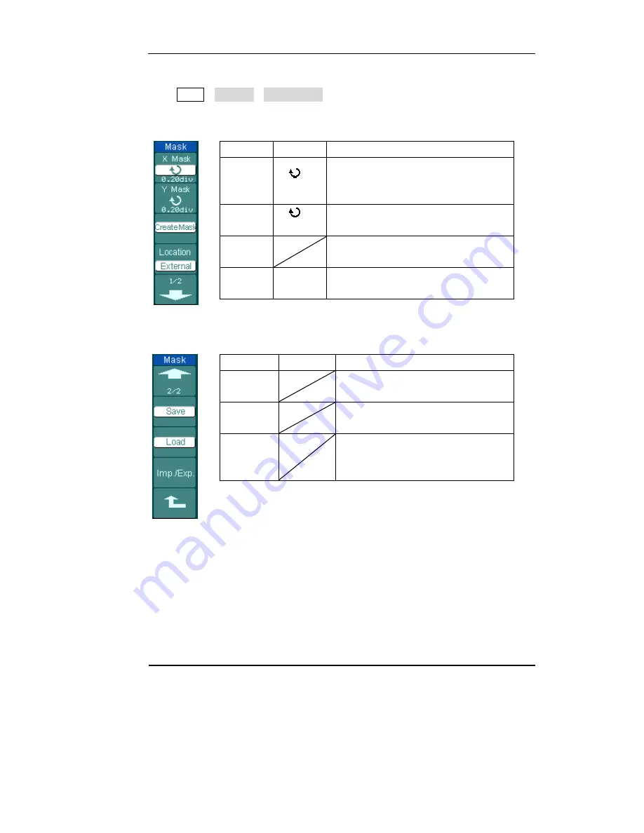
Mask Setting to go to the following menu. 


Figure 2-95    Table 2-60 

Menu Settings

Comments 

X Mask 


< x div>

Set horizontal clearance to the 
waveform 
(0.04div-4.00div) 

Y Mask 


< y div>

Set vertical clearance to the waveform 
(0.04div-4.00div) 

Create 
Mask 


Create a test mask according to the 
above clearance 

Location 

Internal 
External 

Set the memory location of the mask 
files. 


Figure 2-96        Table 2-61 when the save as Internal memory 

Menu Settings

Comments 

Save  


Store created test mask into internal 
memory 

Load  


Recall  mask setting file from 
internal memory 

Imp./Exp. 


Go to import/export menu (same as 
REF import/export menu. See table 
2-10) 


Summary of Contents for DS1000C

Page 1: ...User s Guide RIGOL Publication number DS1 071026 October 2007 DS1000 Series Digital Oscilloscopes DS1000CD DS1000C DS1000MD DS1000M Copyright RIGOL Technologies Inc 2007 All Rights Reserved...

Page 2: ......

Page 3: ...s are protected by patent law in and outside of P R China z Information in this publication replaces that in all previously corresponding material z RIGOL Technologies Inc reserves the right to modify...

Page 4: ...leads while they are connected to a voltage source Ground the instrument This oscilloscope is grounded through the protective earthing conductor of the power cord To avoid electric shock the groundin...

Page 5: ...rate with suspected failures If you suspect damage with this product have it inspected by qualified service personnel before further operations Provide Proper Ventilation Refer to the manual s install...

Page 6: ...t could result in damage to this product or other property Terms on the Product These terms may appear on the product DANGER indicates an injury hazard may be immediately accessible WARNING indicates...

Page 7: ...independently or in a 8 bit group z Mono Color TFT LCD Displays at 320 234 resolution z USB storage and printing supports firmware upgradeable via USB connectivity z Adjustable waveform intensity more...

Page 8: ...supports Chinese English characters key in DS1000 Series Digital Oscilloscope accessories z Two 1 5 meter 1 1 10 1 switchable probes z Digital test set Mixed Signal Oscilloscope only DS1xxxxD include...

Page 9: ...derstand the vertical system 2 2 Understand the Horizontal System 2 30 Understand the Trigger System 2 36 To Set Up the Sampling System 2 59 To Set Up the Display System 2 63 To Store and Recall Wavef...

Page 10: ...Example 10 Triggering on a Digital Signal 3 14 CHAPTER 4 PROMPT MESSAGES TROUBLESHOOTING 4 1 Prompting Message 4 1 Troubleshooting 4 3 CHAPTER 5 SUPPORT SERVICE 5 1 CHAPTER 6 APPENDIX 6 1 Appendix A...

Page 11: ...covers the following topics The front panel and user interface To inspect the instrument To perform a functional check To compensate probes To use digital leads Mixed signal oscilloscope only To disp...

Page 12: ...s and buttons The knobs are used most often and are similar to the knobs on other oscilloscopes The buttons not only let you use some of the functions directly but also bring up soft button menus on t...

Page 13: ...al buttons Associated with horizontal MENU Trigger buttons Associated with trigger MENU instant action to set 50 trigger level and FORCE trigger Action buttons Include run control buttons for AUTO and...

Page 14: ...cter figures of buttons and knobs are the same to those on front panel A box around the name of the key denotes MENU function buttons on front panel such as Measure denotes the multi function knob den...

Page 15: ...log and Digital channels Waveform display window Menu Channel 1 Channel 2 Running status Location of waveform window in memory Trigger point in waveform window Digital channels turned on Digital chann...

Page 16: ...the accessories Accessories supplied with the instrument are listed in Accessories in this guide If the contents are incomplete or damaged notify your RIGOL Sales Representative 3 Inspect the instrume...

Page 17: ...play shows the waveform window Push the Storage button select Storage in the top menu box and push the Factory menu box Figure 1 5 WARNNING To avoid electric shock be sure the oscilloscope is properly...

Page 18: ...his push CH1 Probe 10X Figure 1 7 Figure 1 8 Push the AUTO button Within a few seconds you could see a square wave in the display approximately 1 kHz 3 V peak to peak Push the OFF button or push the C...

Page 19: ...ip onto the probe Attach the probe tip to the PROBE COMP connector and the reference lead to the PROBE COMP Ground connector turn on channel 1 and then press AUTO 2 Check the shape of the displayed wa...

Page 20: ...s at this step you may keep the oscilloscope on 2 Connect one end of the flat cable FC1868 to the Logic Analyzer Input connect the other end to Logic Head LH1116 An identifier is located on each end o...

Page 21: ...User s Guide for DS1000 Series 3 Connect a test clip to one lead wire make sure it s connected well Figure 1 11 4 Test your device with the clip Figure 1 12 5 Remember to connect Ground Channel to the...

Page 22: ...sets up vertical horizontal and Trigger controls to display the input signal in the screen for view You may want to adjust the controls manually if necessary to get the best results DS1000 series are...

Page 23: ...and status bar It will help you be familiar with the setting of the vertical parameters Figure 1 14 1 Center the signal on the display with the knob The knob moves the signal vertically and it is cali...

Page 24: ...ely 2 Change the vertical setup and notice that each change affects the status bar differently You can quickly determine the vertical setup from the status bar in the display z Change the vertical sen...

Page 25: ...o the status bar The horizontal knob changes the sweep speed in a 1 2 5 step sequence and the value is displayed in the status bar The time base ranges of the DS1000 series are listed as follows The h...

Page 26: ...key this is especially helpful when the trigger point is far out of the screen and want it to get back to the screen center immediately 3 Press the MENU key to display the TIME menu In this menu you c...

Page 27: ...and notice the changes it makes to the display On the DS1000 series oscilloscopes as you turn the knob or press the 50 menu button two things happen on the display for a short time First the trigger l...

Page 28: ...Source button to select CH1 Press the trigger Slope button to choose Rising Edge Press the trigger Sweep button to select Auto Press the trigger Set Up button to enter secondary menu Figure 1 17 NOTE...

Page 29: ...or Single trigger mode This button has no effect if the acquisition is already stopped Key point Holdoff A time interval before the oscilloscope response to next trigger signal During this holdoff pe...

Page 30: ......

Page 31: ...ing this guide We recommend you perform all of the following exercises so that you could get the most out of the powerful measurement capabilities of your oscilloscope This chapter covers the followin...

Page 32: ...le2 1 Menu Settings Comments Coupling AC DC GND Blocks the DC component of the input Signal Passes both AC and DC components of the input signal Disconnects the input signal BW Limit ON OFF Limits the...

Page 33: ...s 2 2 Back to the previous menu page The followings are the same no more explanation Volts Div Coarse Fine Selects the resolution of the knob Defines a 1 2 5 sequence To change the resolution to small...

Page 34: ...with DC shift Press CH1 Coupling AC to set coupling as AC of CH1 In this setting it blocks the DC component of the input signal The waveform is displayed as Figure 2 3 Figure 2 3 Press CH1 Coupling D...

Page 35: ...waveform is displayed as Figure 2 4 Figure 2 4 Press CH1 Coupling GND to set coupling as GND of CH1 In this setting it disconnects the input signal The screen displays as Figure 2 5 Figure 2 5 GND cou...

Page 36: ...OFF to set up bandwidth limit to OFF status The oscilloscope is set to full bandwidth and the high frequency component in the signal will pass The waveform is displayed as Figure 2 6 Press CH1 BW Limi...

Page 37: ...voltage levels at the probe tip To change or check the probe attenuation setting press the CH1 or CH2 button according to which channel you are using toggle the Probe soft button to change the attenu...

Page 38: ...ts Div and it makes the vertical scaling in a 1 2 5 step sequence from 2mV div 5mV div 10mV to 5 V div Fine This setting changes the vertical scale to small steps between the coarse settings It will b...

Page 39: ...s the displayed waveform 180 degrees as respect to the ground level When the oscilloscope is triggered on the inverted signal the trigger is also inverted Figure 2 10 and 2 11 show the changes after i...

Page 40: ...7 User s Guide for DS1000 Series Digital Filter Press CH1 Digital filter display the digital filter menu Turn knob to set high and low limit of frequency Turn off digital filter Turn on digital filter...

Page 41: ...the digital filter Turn off the digital filter Filter Type Setup as LPF Low Pass Filter Setup as HPF High Pass Filter Setup as BPF Band Pass Filter Setup as BRF Band Reject Filter Upper limit frequen...

Page 42: ...be measured by grid and cursor Figure 2 15 Figure 2 16 Table 2 5 Menu Settings Comments Operation A B A B A B FFT Add source A and source B Subtract source B from source A Multiply source B by source...

Page 43: ...Characterizing noise in DC power supplies z Analyzing vibration Figure 2 17 Table2 6 Menu Settings Comments Operate A B A B AxB FFT Add source A to source B Subtract source B from source A Multiply so...

Page 44: ...orm component magnitude values To minimize the DC component choose AC Coupling on the source signal 2 To reduce random noise and aliases components in repetitive or single shot events set the oscillos...

Page 45: ...noise with a relatively slow varying spectrum Hanning Hamming Better frequency poorer magnitude accuracy than Rectangular Hamming has slightly better frequency resolution than Hanning Sine periodic an...

Page 46: ...channel Select LA as REF channel Mixed Signal Oscilloscope Location Internal External Select memory location in scope Select memory location out scope Save Save REF waveform Imp Exp Go to import expor...

Page 47: ...following menu Figure 2 20 Table 2 10 Menu Settings Comments Explorer Path Directory File Switch to Path directory or file Export Export the REF file from internal memory to export memory see table 2...

Page 48: ...for DS1000 Series Export Press REF Imp Exp Export and go to the following menu Figure 2 22 Table 2 11 Menu Settings Comments Move the cursor up Move the cursor down To delete chosen letter Save Execut...

Page 49: ...EF Save and go to the following menu Figure 2 24 Table 2 12 Menu Settings Comments Explorer Path Directory File Switch among Path Directory and File New File Folder Set up new file in Path and File Se...

Page 50: ...File or New Folder and go to the following menu Figure 2 26 Table 2 13 Menu Settings Comments Move the cursor up Move the cursor down To delete chosen letter Save Execute the operation The figure of k...

Page 51: ...000 Series Import Press REF Import and go to the following menu Figure 2 28 Table 2 14 Menu Settings Comments Explorer Path Directory File Switch among Path Directory and File Import Import the REF fi...

Page 52: ...button 1 to select CH1 CH2 MATH FFT or LA Mixed Signal Oscilloscope to choose the REF channel you want 3 Turn vertical and vertical to adjust the REF waveform to a suitable position 4 Select the save...

Page 53: ...D8 set up channel group D15 D8 see 2 17 Current D15 D0 Select channel by turning knob Threshold TTL CMOS ECL User Select mode of whole digital channels The threshold voltage can set by user when in u...

Page 54: ...ies Figure 2 32 2 Set threshold mode of digital channels Press LA Threshold select logic standard or User to define your own threshold voltage The figure of menu shows as follow Figure 2 33 Select run...

Page 55: ...RIGOL Copyright RIGOL Technologies Inc 2007 2 25 User s Guide for DS1000 Series Threshold explanation LOGIC STANDARD THRESHOULD VLOTAGE TTL 1 4V CMOS 2 5V ECL 1 3V User 8V to 8V...

Page 56: ...l D7 D0 Turn on or off single channel of D7 D0 D7 D0 Turn on Turn off Turn on or off all 8 channels together Size Display 8 channels in a single screen Display 16 channels in a single screen Reset Res...

Page 57: ...c channels Press LA D7 D0 D7 D0 Turn On Turn Off or D15 D8 D15 D8 Turn On Turn Off will force to turn all the channels on off If you want to turn on off any single channel instead select the Channel b...

Page 58: ...selected press OFF will turn the channel off as well and the key backlight also goes off Table 2 18 Status Indicator Channel Mode Settings DS1000 MONO DS1000 COLOR Channel 1 CH1 ON Selected OFF CH1 b...

Page 59: ...ms displayed Pressing this knob will clear the channel offset to zero Exclude digital channels in the Mixed Signal Oscilloscope 2 Using vertical knob The vertical can change the vertical sensitivity o...

Page 60: ...to expand or contract about the screen center Horizontal position changes the displayed waveform position relative to the trigger point The Horizontal Knobs The horizontal knob adjusts the horizontal...

Page 61: ...tal control Menu Settings Comments Delayed ON OFF Turn on Delayed Scan mode Turn off the Delayed Scan mode Time Base Y T X Y Roll Show the relative relation between vertical voltage and horizontal tim...

Page 62: ...l 1 in the horizontal axis and channel 2 in the vertical axis Roll Mode In this mode the waveform display rolls from right to left No trigger or horizontal offset control of waveforms is available dur...

Page 63: ...ed Scan window The following steps show you how to use Delayed Scan 1 Connect a signal to the oscilloscope and obtain a stable display 2 Press horizontal MENU Delayed ON or press horizontal knob to en...

Page 64: ...change the position of the expanded portion z Turn the horizontal knob to adjust the Delayed Scan resolution z To change the main time base you must turn off the Delayed Scan mode z Since both the mai...

Page 65: ...and channel 2 in the vertical axis Y the oscilloscope uses a none trigger acquisition mode data is displayed as dots Figure 2 40 X Y display format The following modes or functions will not work in X...

Page 66: ...to acquire data while waiting for the trigger condition to occur After it detects a trigger the oscilloscope continues to acquire enough data so that it can draw the waveform to the right of the trigg...

Page 67: ...en the trigger input passes through a specified voltage level in the specified slope direction Pulse Use this trigger type to catch pulses with certain pulse width Video Use video trigger on fields or...

Page 68: ...ine D15 D0 Select CH1 as trigger signal Select CH2 as trigger signal Select EXT TRIG as trigger signal Select attenuated EXT TRIG 5 as trigger signal Select power line as trigger signal Select a digit...

Page 69: ...ettings Comments Source CH1 CH2 EXT EXT 5 D15 D0 Selects CH1 as trigger signal Select CH2 as trigger signal Select EXT TRIG as trigger signal Select attenuated EXT TRIG 5 as trigger signal Select a di...

Page 70: ...ents Sweep Auto Normal Single Acquire waveform even no trigger occurred Acquire waveform when trigger occurred When trigger occurs acquire one waveform and then stop Set Up To go to Set Up menu see ta...

Page 71: ...TRIG as trigger source Select EXT TRIG 5 as trigger source Polarity Normal polarity Inverted polarity Triggers on negative going sync pulses Triggers on positive going sync pulses All Lines Line Num...

Page 72: ...en field Menu Settings Comments Standard PAL SECAM NTSC Select Video standard Set Up To go to set up menu see table 2 39 Key points Sync Pulses When Normal Polarity is selected the trigger always occu...

Page 73: ...RIGOL Copyright RIGOL Technologies Inc 2007 2 43 User s Guide for DS1000 Series Figure 2 49 Video Trigger Field Synchronization...

Page 74: ...er source Set channel 2 as trigger source Set EXT channel as trigger source Set EXT 5 as trigger source When Set slope condition Time Time Set Set slope time Figure 2 51 Table 2 27 Page Two Menu Setti...

Page 75: ...nc 2007 2 45 User s Guide for DS1000 Series Note Slope time can be set from 20ns to 10s When a signal meets the trigger condition scope will execute the acquisition You can adjust LEVEL A LEVEL B or b...

Page 76: ...nels The options are as follows Edge Pulse Slope and video The info of the trigger level of the two channels will be displayed on the upper right of the screen Figure 2 52 Table 2 28 Trigger Type Edge...

Page 77: ...Set trigger mode for Channel 2 Type Pulse Set Pulse Trigger for the channel When Pulse width less than Pulse width more than Pulse width equal to Pulse width less than Pulse width more than Pulse widt...

Page 78: ...ts Select CH1 CH2 Set trigger mode for Channel 1 Set trigger mode for Channel 2 Type Slope Set Slope Trigger for the vertical channel When Set trigger condition Figure 2 56 Table 2 32 Trigger Type Slo...

Page 79: ...ty Normal polarity Inverted polarity Triggers on negative going sync pulses Triggers on positive going sync pulses Figure 2 58 Table 2 34 Trigger Mode Video Page two Menu Settings Comments ALL lines L...

Page 80: ...stop Set Up To go to set up menu see table 2 40 Key Points H High Logic high voltage is higher than threshold setting L Low Logic low voltage is lower than threshold setting X Ignore Don t care If al...

Page 81: ...ts Select D15 D0 Choose digital channel for Duration Trigger Code H L X High Low Ignore Qualifier Set time limit terms Figure 2 61 Table 2 37 Page Two Menu Settings Comments Time Time Setting Set dura...

Page 82: ...high voltage is higher than threshold setting L Low Logic low voltage is lower than threshold setting X Ignore Don t care If all the channels are ignored the oscilloscope won t be triggered Qualifier...

Page 83: ...et When in Alternative trigger you can make different settings according to selected different trigger modes Figure 2 62 Table 2 38 Settings for trigger coupling trigger sensitivity and holdoff Menu S...

Page 84: ...hnologies Inc 2007 User s Guide for DS1000 Series Figure 2 64 Table 2 40 Settings only for holdoff Menu Settings Comments Holdoff Holdoff Setting Set time slot before another trigger event Holdoff Res...

Page 85: ...til Holdoff ends For instance To trigger on the first pulse on a group of them users can set the holdoff time to Pulse cluster width Figure 2 65 Trigger Holdoff To use trigger Holdoff 1 Press the trig...

Page 86: ...trigger on a larger signal z AC Line AC power can be used to display signals related to the power line frequency such as lighting equipment and power supply devices The oscilloscope gets triggered on...

Page 87: ...eject and HF Reject AC AC coupling blocks DC components DC DC coupling passes both AC and DC components LF Reject LF Reject coupling blocks DC component and attenuates all signal with a frequency lowe...

Page 88: ...of noise from the physical world and get the stable trigger the trigger circuit has adopted Stickiness In DS1000 series the stickiness is adjustable from 0 1div 1 0div which means when it sets to 1 0...

Page 89: ...u Settings Comments Acquisition Normal Average Peak Detect Normal Acquisition mode Average Acquisition mode Peak Detect Acquisition mode Averages 2 to 256 Step by multiple of two Set average times fro...

Page 90: ...ll change in conjunction with the setting of Acquire menu Figure 2 68 Signal that contains noise and without average sampling Figure 2 69 Display signal after average sampling Note z Select Real time...

Page 91: ...r z To Avoid signal aliasing select Peak Detect Acquisition Figure 2 70 Signal with Peak Detect Acquisition The Peak Detect effect is shown as the figure above Stop Acquisition When the scope is acqui...

Page 92: ...equivalent 25Gsa s This mode is good for observing repetitive signals and it is not recommended for single shot or pulse Normal Oscilloscope acquires signal by equal time interval Average Acquisition...

Page 93: ...up the menu for the settings of the display system Figure 2 72 Table 2 42 Menu Setting Comments Type Vectors Dots Display waveforms as vectors Display waveforms as dots Clear Clear all existing wavefo...

Page 94: ...een Normal Invert Set to normal mode Set to invert color display mode Key points Display type Display type includes Vector and Dot In vectors type oscilloscope connects dots through digital interpolat...

Page 95: ...tup file bitmap and CSV file in external memory can be created and deleted System supports English Chinese key in Waveform and setup the menu as following Figure 2 75 Table 2 44 Menu Settings Comments...

Page 96: ...anage menu see table 2 50 For CSV the menu as following Figure 2 77 Table 2 46 Menu Settings Comments Storage Waveform Setups Bitmap CSV Factory Store or recall waveform Store or recall setups Create...

Page 97: ...form Setups Bit map CSV Factory Store or recall waveform Store or recall setups Create or delete bit map files Create or delete CSV files Recall factory setups Para Save On Off Save the current oscill...

Page 98: ...Internal to go to the following menu Figure 2 79 Table 2 48 Menu Settings Comments Internal Int_00 N Int_09 N Set up the location of files in internal memory Load Recall waveform files and setup file...

Page 99: ...Figure 2 80 Table 2 49 Menu Settings Comments Explorer Path Directory File Switch among Path Directory and File New File Folder To create new file or folder Delete File Folder Delete file Folder Load...

Page 100: ...2 50 Menu Settings Comments Explorer Path Directory File Switch among Path Directory and File New folder To create new folder same as new files see table 2 13 Delete File Delete file Load Recall wavef...

Page 101: ...e for DS1000 Series Rename Press Storage Disk Mana Rename to go to the following menu Figure 2 84 Table 2 52 Menu Settings Comments To move the cursor up To move the cursor down To delete chosen lette...

Page 102: ...the waveform and setup Load Recall saved waveform setup and default settings Save Save waveform and setups NOTE 1 Select Save stores not only the waveforms but also the current settings of the oscillo...

Page 103: ...tton to pop up the menu for the settings of the Utility system Figure 2 87 Table 2 53 Menu Setting Comments I O setting Setup I O configuration Sound ON OFF Switch beeper sound on off Counter OFF ON T...

Page 104: ...Cal ON OFF Turn on fast calibration Turn off fast calibration Self Cal Execute Self calibration Service Go to service menu Preferenc Go to preference menu Note Fast Cal When turn on the fast cal funct...

Page 105: ...nc 2007 2 75 User s Guide for DS1000 Series The I O setup Press Utility I O setting to go to the following menu Figure 2 90 Table2 56 Menu Display Comments RS 232 Baud 300 38400 Set RS 232 baud rate a...

Page 106: ...his function can extend the life of LCD backlight tube Expand reference When changing the volts div for channels you can have the signal expand or compress around the signal ground level or the center...

Page 107: ...racy at any time run this calibration if the ambient temperature changes by 5 C or more Before running this procedure do these steps 1 Disconnect any probes or cables from all channel inputs otherwise...

Page 108: ...ce CH1 CH2 Select Pass Fail test on CH1 Select Pass Fail test on CH2 Operate RUN STOP Pass Fail test stopped press to run Pass Fail test running press to stop Msg display ON OFF Turn on Pass Fail info...

Page 109: ...00div Y Mask y div Set vertical clearance to the waveform 0 04div 4 00div Create Mask Create a test mask according to the above clearance Location Internal External Set the memory location of the mas...

Page 110: ...ide for DS1000 Series Figure 2 97 Table 2 62 when the save as external memory Menu Settings Comments Save Go to save menu same as REF save menu See table 2 12 Load Go to load menu see table 2 63 Impor...

Page 111: ...eries Load Press Utility Pass Fail Mask Setting Load to go to the following menu Figure 2 98 Table 2 63 Menu Settings Comments Explorer Path Directory File Switch among Path Directory and File Load Re...

Page 112: ...connect to another circuit to fulfill the function Before connecting external circuit make sure the maximum voltage current do not exceed the internal photoMOS relay s rating 400V 100mA DS1000 series...

Page 113: ...DS1000 series oscilloscopes support external printers Press Utility Print set to go to the following menu Figure 2 100 Table 2 64 Menu Settings Comments Print Execute print function Inverted ON OFF in...

Page 114: ...out keeping an eye watching it Press Utility Record Mode Record to go to the following menu Waveform recorder Record the waveforms with specified interval Figure 2 101 Table2 65 Menu Settings Comments...

Page 115: ...y stopped press to Start playback Playing press to stop Play mode Set repeat play mode Set single time play mode Interval 1 00ms 20s Set up interval Figure 2 103 Table 2 67 Menu Settings Comments Star...

Page 116: ...rt Frame 1 1000 Set first frame to be saved End Frame 1 1000 Set last frame to be saved Location Internal external Set up Store location Figure 2 105 Table 2 69 when the save to Internal memory Menu S...

Page 117: ...de for DS1000 Series Figure 2 106 Table 2 70 when the save as external memory Menu Settings Comments Save Go to save menu same as REF save menu See table 2 12 Load Go to load menu see table 2 63 Impor...

Page 118: ...face 2 Screen Test Press this soft button to run Screen Test program The screen turns black or white in sequence Mono and the screen turns red green and blue in sequence Color when keep pressing the R...

Page 119: ...when pressing a key 2 The blocks will reverse its color to red Color models or black Mono models when the corresponding key or knob get pressed and the color will keep reversed during the test 3 Key...

Page 120: ...0 Copyright RIGOL Technologies Inc 2007 User s Guide for DS1000 Series Language The DS1000 series oscilloscopes have multi language user menu choose as your desire Press Utility Language to select the...

Page 121: ...loscopes provide 20 parameters for auto measurement including Vpp Vmax Vmin Vtop Vbase Vamp Vavg Vrms Overshoot Preshoot Freq Period Rise Time Fall Time Delay1 2 Delay1 2 Width Width Duty Duty That s...

Page 122: ...Vmin Measure minimum voltage of a waveform Vpp Measure Peak to Peak Voltage Vtop Measure a flat top voltage of a square waveform Page 2 for voltage measurements Table 2 74 Menu Settings Comments Vbase...

Page 123: ...or Time Measurements Figure 2 113 Table 2 76 Menu Settings Comments Period Measure Period of a waveform Freq Measure Frequency of a waveform Rise time Measure Rise Time of a rising edge Fall time Meas...

Page 124: ...ls delay between two channels at the rising edge Delay1 2 Measure the signals delay between two channels at the falling edge NOTE The results of the automatic measurements will be displayed on the bot...

Page 125: ...een 3 Select parameters page for measuring You could select voltage or time parameters pages by pressing soft button as follows Measure Voltage or time Vmax Vmin 4 To get the measured value on the scr...

Page 126: ...ge measured over the entire waveform Vmin The minimum amplitude The most negative peak voltage measured over the entire waveform Vamp Voltage between Vtop and Vbase of a waveform Vtop Voltage of the w...

Page 127: ...f the first pulse in the waveform takes to rise from 10 to 90 of its amplitude Fall Time Time that the falling edge of the first pulse in the waveform takes to fall from 90 to 10 of its amplitude Widt...

Page 128: ...gnal Source as the channel for measuring 2 Track In this mode the screen displays two cross cursors The cross cursor sets the position on the waveform automatically You could adjust cursor s horizonta...

Page 129: ...Oscilloscope In this mode the oscilloscope measures the cursors coordinate values for Y or X and the increment between the two cursors To do manual Cursor Measurements please do as the following steps...

Page 130: ...on the midpoint of screen Voltage cursor centered on channel ground level Position of Cursor 2 same as above Horizontal space between cursor 1 and 2 X Time between cursors 1 X units in Hz kHz MHz GHz...

Page 131: ...lay and measure the vertical parameters Usually it is used to measure the Volts When the source is set as function the units are assigned to the function Cursor X Cursors X appear as vertical lines on...

Page 132: ...tifunctional knob to move cursor B horizontally In cursor track mode the cursors move together with the selected waveform To do Track mode Cursor Measurements follow these steps 1 Select the Track mod...

Page 133: ...tion of Cursor 1 Time cursor centered on the midpoint of screen Voltage cursor centered on channel ground level Position of Cursor 2 Time cursor centered on the midpoint of screen Voltage cursor cente...

Page 134: ...tings Comments Mode Auto Display the cursors for the current automatic measuring See the following figure Figure 2 123 Auto Measure Mode of Cursor Measurement There will be no cursor display if no par...

Page 135: ...following menu will appear Figure 2 124 Table 2 84 Menu Settings Comments Multi Cycle Press to display multi cycle waveform on the screen Single Cycle Press to display single cycle waveform on the sc...

Page 136: ...V div Adjusted Volts Div Coarse Bandwidth limit Full Signal Invert OFF Horizontal position Center Horizontal S div Adjust to right position Trigger type Edge Trigger source Find the channel with input...

Page 137: ...imize the display of the waveform you could adjust these controls manually to meet your requirements Selecting Automatic Measurements The oscilloscope could take automatic measurements on most signals...

Page 138: ...vertical and the horizontal scale by turning the knobs to appropriate ranges for display 3 Press the CH1 button to select CH1 and turn the vertical knob to adjust the vertical position of CH1 s wavefo...

Page 139: ...weep to select Single z Press Set Up Coupling to select DC 3 Turn the vertical and horizontal knobs to adjust the Volts Div and the Time base in a proper range for the signal 4 Turn the knob to adjust...

Page 140: ...stable display 3 Improve the trigger by setting the Coupling 1 Press the MENU in the Trigger control area 2 Press Set Up Coupling LF Reject or HF Reject HF Reject High frequency reject adds a low pass...

Page 141: ...easure To use average follow these steps z Press soft button as Acquire Acquisition Average z Toggle the Averages soft button to select the number of averages that best eliminates the noise from the d...

Page 142: ...he cursors to quickly make time and voltage measurements on a waveform Measuring the Frequency of the First Sinc Waveform Peak To measure the ring frequency at the rising edge of a signal do these ste...

Page 143: ...s 1 Press Cursor key to see the Cursor menu 2 Press Mode to set Manual mode 3 Press Type to select Y 4 Turn knob to place cursor A on the first peak of the wave 5 Turn knob to place cursor B on the se...

Page 144: ...channel 1 probe to the input of the network and connect the channel 2 probe to the output 3 If the channels are not displayed press the CH1 and CH2 buttons 4 Press the AUTO button 5 Adjust the vertica...

Page 145: ...Sin A B or C D where phase shift in degrees between the two signals From the formula above you could get arcsine A B or arcsine C D If the main axis of the ellipse is at I and III quadrant must be in...

Page 146: ...rea to see the Trigger menu 2 Press Mode to select Video mode 3 Press Source to select CH1 as trigger source 4 Press Polarity to select 5 Press Sync as Odd Field or Even Field 6 Adjust the to set trig...

Page 147: ...e the trigger menu 2 Press Mode to select Video mode 3 Press Source to select CH1 as trigger source 4 Press Polarity to select 5 Press Sync to select Line Num 6 Turn knob to trigger on a specified lin...

Page 148: ...Cursor measurement FFT measurements include amplitude measurement Vrms or dBVrms and Frequency measurement Hz Do these steps as follow 1 Press Cursor Manual 2 Press Type to select X or Y 3 Press Sourc...

Page 149: ...rammable output can be used for external automatic control applications such as the automatic failure product kick out in a production line The output is built in as a standard feature and is opticall...

Page 150: ...riggering system was being used The two triggering ways are only allowed to a digital signal Pattern Do the steps as following 1 Press the MENU key in the triggering control area to see the trigger me...

Page 151: ...see the trigger menu 2 Press Mode to select Duration mode 3 Turn knob to select the channel you want to set 4 Press Code to set Code Setting H L or X 5 Press Qualifier to set time limit terms 6 Press...

Page 152: ......

Page 153: ...the vertical knob No active cursor Prompts that you haven t set the cursor source while using the Track cursor measurements Delayed scale at limit Prompts that it is at the full range of horizontal re...

Page 154: ...or settings Measurement already selected Prompts that the measurement parameter you pressed is already displayed on screen Dot display only Prompts that you could only use Dots type for display under...

Page 155: ...bes connected with the object being tested 4 Check the circuit generates signal on the test point 5 Repeat the acquisition 3 The measurement result is 10 times higher or lower than the value expected...

Page 156: ...eover you could push AUTO button to display the waveform on screen 6 After the Acquisition is set to Averages or Display Persistence is set ON the waveform refreshes slowly It is normal in these setti...

Page 157: ...respective period RIGOL will provide repair or replacement as described in the complete warranty statement To arrange for service or obtain a copy of the complete warranty statement please contact yo...

Page 158: ...tact your local distributor Domestic Please call Tel 86 10 80706688 Fax 86 10 80720067 9 00 am 5 00 pm from Monday to Friday Or by e mail support rigol com Or mail to RIGOL Technologies Inc 156 CaiHe...

Page 159: ...ure 2 You must perform the Self Cal operation accessible through the Utility menu if the operating temperature changes by more than 5 C All specifications are guaranteed unless noted typical Specifica...

Page 160: ...nnel 512K samples for each channel Record Length 512K samples Scan speed Range Sec div 5ns div 50s div DS1102XX DS1062XX 10ns div 50s div DS1042XX 20ns div 50s div DS1022XX 1 2 5 Sequence Sample Rate...

Page 161: ...0MHz Lower Frequency Limit AC 3dB 5Hz at input BNC Rise Time at BNC typical 3 5ns 5 8ns 8 7ns 14ns On 100M 60M 40M 25M respectively DC Gain Accuracy 2mV div 5mV div 4 Sample or Average acquisition mod...

Page 162: ...div delayed trigger 6div Trigger Holdoff range 100ns 1 5s Set Level to 50 Typical Input signal frequency 50Hz Edge Trigger Edge trigger slope Rising Falling Rising Falling Pulse Trigger Trigger condit...

Page 163: ...rms Overshoot Preshoot Freq Period Rise Time Fall Time Width Width Duty Duty Delay1 2 Delay1 2 General Specifications Display Display Type 5 7 in 145 mm diagonal TFT Liquid Crystal Display Display Res...

Page 164: ...dity Humidity 35 40 60 relative humidity Operating 3 000 m or below Altitude Non operating 15 000 m or below Mechanical Width 303mm Height 154mm Size Depth 133 mm Without package 2 4 kg Heavy Packaged...

Page 165: ...f 300 V CAT II when the switch is in the 10X position 2 A set of Digital probe components mixed signal oscilloscopes include A data cable Model FC1868 An active logic head Model LH1116 Twenty test wir...

Page 166: ...ent requires cleaning disconnect it from all power sources and clean it with a mild detergent and water Make sure the instrument is completely dry before reconnecting it to a power source To clean the...

Page 167: ...ng 2 4 Cleaning 6 8 Coarse Fine 1 14 2 8 Color Test 2 88 Cursor 2 98 Cursor Measurements 2 98 3 6 D DC Coupling 2 4 Display 6 5 Display System 2 63 Duration Trigger 2 51 E Edge Trigger 2 38 Envelope 2...

Page 168: ...1 Pulse Trigger 2 39 R Random Noise 3 4 Realtime Sampling 2 62 Rectangle Window 2 15 REF 2 16 Roll Mode Display 2 32 RUN STOP 2 105 S Sampling System 2 59 Save and Recal 2 65 Screen Test 2 88 Self Ca...

Reviews: