background image

R41Z-EVAL User Guide 


Rev 2.0 


11.


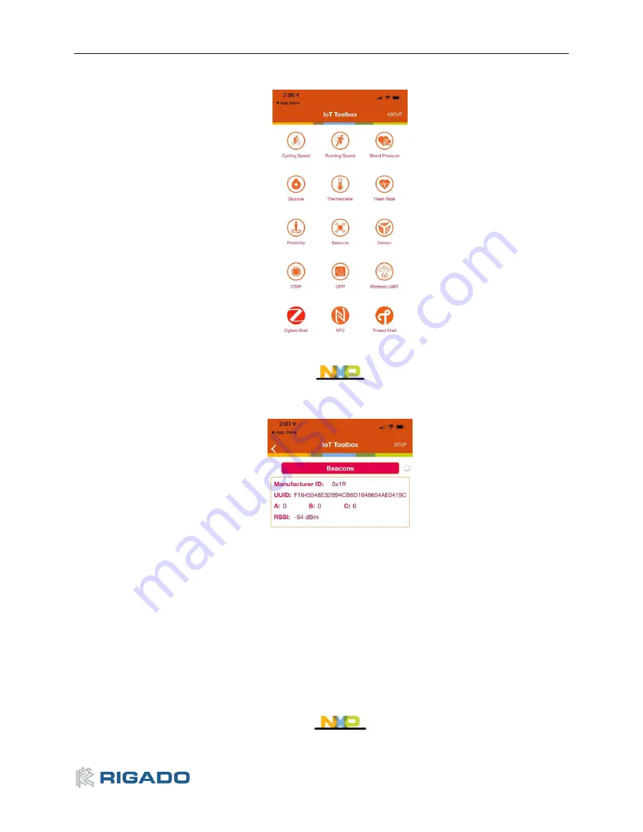
Open the NXP IoT Toolbox mobile app on your mobile device

, and tap the “Beacons” icon:


Figure 13 

 NXP IoT Toolbox mobile app 

12.


Observe the beacon RSSI increase as you move the mobile device closer to the R41Z-EVAL. 


Figure 14 

 Advertising Beacon 

Summary of Contents for R41Z-EVAL

Page 1: ...R41Z EVAL User Guide ...

Page 2: ...14 6 2 Debug Interface 15 6 2 1 OpenSDA Interface 15 6 2 2 Reset Button 15 6 2 3 External Debug Header 15 6 3 Peripherals 17 6 3 1 Expansion Headers 17 6 3 2 IR LED Provision 18 6 3 3 User LEDs 18 6 3 4 Thermistor 19 6 3 5 User Buttons 19 6 3 6 SPI Flash 20 6 3 7 I2 C Acceleration Magnetometer Sensor 21 6 4 R41Z Module 22 6 4 1 32 768kHz Oscillator 22 Related Documents 23 Life Support and other Hi...

Page 3: ...combination acceleration magnetometer sensor and an external 4Mbit flash module Arduino form factor headers provide access to 16 GPIO and 6 analog inputs This allows for easy use of the Rigado R41Z Shields as well as many existing Arduino shields Current sense resistors allow for measuring current into the R41Z module and into the shield 2 1 Key Features R41Z Thread Bluetooth Module On board progr...

Page 4: ...ication MCUXpresso SDK An open source software development kit SDK built specifically for your processor and evaluation board selections MCUXpresso Config Tools A comprehensive suite of system configuration tools including pins clocks Peripherals and more NXP IoT Toolbox IoT Toolbox is an all in one application capable of demonstrating NXP s Bluetooth LE Zigbee and Thread capabilities through the ...

Page 5: ... login to an existing account 2 Download and install the NXP Semiconductors IoT Toolbox app on an available iOS or Android device The app is available from the respective app stores This app will be used to connect to the R41Z EVAL board loaded with the SDK examples 3 Download and install the MCUXpresso IDE on a PC Windows macOS and Linux are supported 4 Download and install the MCUXpresso Config ...

Page 6: ... 0 3 5 2 Try an Example Import and run an example from the SDK 1 In the lower left pane click on Import SDK example s 2 Click on the frdmkw41z under Available boards then click Next Figure 3 Import example Figure 4 Select board ...

Page 7: ...e next screen select the example then click Finish In this case we ll use the Bluetooth Beacon 4 Application source code is in the project tree under the source directory Figure 6 Example source code Figure 5 Select Bluetooth Beacon example ...

Page 8: ...2 0 5 5 Click the hammer icon to build the project 6 Click the bug icon to start debugging 7 Select the J Link OpenSDA debug probe and click OK Figure 9 Debug probe selection Figure 7 Build the example Figure 8 Start debugging ...

Page 9: ...ev 2 0 6 8 Accept the OpenSDA terms of use Figure 10 OpenSDA Terms of Use 9 Click the Play icon to run the application Figure 11 Run the example 10 Observe the blue LED flashing on the R41Z EVAL board Figure 12 Flashing LED ...

Page 10: ...pen the NXP IoT Toolbox mobile app on your mobile device and tap the Beacons icon Figure 13 NXP IoT Toolbox mobile app 12 Observe the beacon RSSI increase as you move the mobile device closer to the R41Z EVAL Figure 14 Advertising Beacon ...

Page 11: ...d in the file app_config c Advertising Data static const uint8_t adData0 1 gapAdTypeFlags_t gLeGeneralDiscoverableMode_c gBrEdrNotSupported_c static uint8_t adData1 26 Company Identifier mAdvCompanyId Beacon Identifier mBeaconId UUID mUuid A 0x00 0x00 B 0x00 0x00 C 0x00 0x00 RSSI at 1m 0x1E ...

Page 12: ... and Blue User LEDs Thermistor External Debugger Header Peripheral Current Measurement Header R41Z Module Power Configuration Jumpers User Button2 User Button5 User Button3 User Button4 Breakout Headers OpenSDA Debug Interface Reset Button USB Power Regulator Power Switch Power Protection Diodes Ext Power Micro USB for Power and Debug Board Current Measurement Header Power Configuration Switch Bre...

Page 13: ...ected However since the diodes do cause approximately a 0 3V drop in source voltage there is the option to bypass the diodes via solder jumpers Care should be taken to not damage the supplies or Evaluation board when the protection is by passed If necessary the LDO regulator can be disabled in order to allow for USB based debugging while powering the R41Z from either an external source or a coil c...

Page 14: ...egulated power to other peripheral devices Suitable for small applications powered directly from a lithium ion battery 2 If total power consumption is low the R41Z module can provide a regulated power rail to supply other devices Boost 0 9V 1 8V 1 8V 3 0V 1 DC DC Converter operates if boost mode Internal power rails are sourced and regulated by the R41Z module An externally available power rail V1...

Page 15: ...pplied Use this option when using Bypass Mode PSWITCH ON When in Buck mode the DC DC Converter will automatically start when power is applied Use this option when using Boost Mode 3 Regulator On When USB is connected the LDO regulator will supply power to the Evaluation Board Regulator Off When USB is connected the LDO regulator will not supply power 4 Regulator 3 6V When USB is connected the LDO ...

Page 16: ...igure 18 Power Configuration Jumpers Default The 4 jumpers used to switch between Buck and Boost DC DC modes are labeled JMODE JLP J1P5 and J1P8 See the figures below for how to set these jumpers along with the correct Power Configuration Switch positions DC DC Mode Selection Mode PWR Config SW JMODE JLP J1P5 J1P8 Bypass Pos 1 Bypass Default Pos 2 OFF Default Pos 4 REG 3 6V Buck Default Open Defau...

Page 17: ... or external power directly powers both the R41Z module but also all onboard peripheral devices and provides expansion shield power However when operating in either Buck or Boost DC DC Mode the R41Z module supplies regulated power to the peripheral devices and shield This makes it difficult to directly measure the power consumption of just the R41Z module The Evaluation Board features two current ...

Page 18: ...enSDA application apply power to the board while holding the reset button The Evaluation Board will appear as mass storage device named Maintenance onto which the OpenSDA application binary can be copied 6 2 2 Reset Button The reset button is primarily meant to be used to reset the R41Z module It is also used to put the OpenSDA interface into Maintenance mode to allow for different Debug Applicati...

Page 19: ...aluation Board supports the use of external debuggers A standard 10 pin SWD JTAG header is provided with the following pinout to the target R41Z module 0 Pin Usage 1 V1P8 R41Z I O voltage 2 SWDIO 3 GND 4 SWCLK 5 GND 6 N C 7 N C 8 N C 9 GND 10 RESET_n Table 5 External Debugger Header Pinout ...

Page 20: ...dditional peripherals of the user s choice to be added in the form of expansion shields These headers share I O connections to the R41Z module with the existing onboard peripherals If an on board peripheral will interfere with the operation of a shield jumpers can be used to disconnect the on board device 6 3 1 Expansion Headers Figure 22 Expansion Header Pinout ...

Page 21: ...OT 23 NPN BJT Resistor R45 is not provided on the board to avoid pulling down PTB1 Figure 23 Schematic IR LED 6 3 3 User LEDs The R41Z Evaluation Board features an RGB LED and a separate blue LED Since the GPIO used are shared with the expansion header solder jumpers are provided to disconnect the LEDs if required Since the LEDs are powered from the peripheral power bus VIO they will be powered di...

Page 22: ...ns requiring temperature measurement Figure 25 Schematic Thermistor and ADC Mode Selection 6 3 5 User Buttons Two mechanical buttons SW3 SW4 and two capacitive touch buttons SW2 SW5 are provided on the Evaluation Board The Capacitive touch buttons enable easy development of applications that make use of the R41Z s Touch Sense Input TSI module Figure 26 Schematic User Buttons ...

Page 23: ...ith signals shared with the expansion headers When using multiple Chip Select CS signals this allows the same SPI bus to be used with both the Flash module and one or more SPI devices on an expansion shield However some signals are also shared with the TSI user buttons SPI Flash Signal R41Z I O SPI CLK PTC16 SPI MOSI PTC17 SPI MISO PTC18 Flash CS_n PTC19 Table 6 SPI Port Signals Figure 27 Schemati...

Page 24: ...luation Board When in I2C mode the address of the sensor can be set using external pull up and pull down resistors The signals used for the I2 C bus are shared with the expansion headers Because of the addressed nature of I2 C it is possible to use this same bus to connect to additional devices on a shield Combo Sensor Address Address SA1 SA0 0x1C 1 0 0x1D 0 1 0x1E 0 0 0x1F Default 1 1 Table 7 Com...

Page 25: ...aintain high accuracy Bluetooth time keeping in low power modes an external 32 768kHz crystal oscillator is provided Some applications may not require this external oscillator in which case a set of jumpers can be used to connect these I O to the expansion headers The R41Z module features programmable capacitors which can be used in place of external capacitors However external capacitors are prov...

Page 26: ...OF FITNESS FOR USE IN HIGH RISK ENVIRONMENTS The customer using this product in a High Risk Environment agrees to indemnify and defend Rigado from and against any claims and damages arising out of such use Environmental 9 1 RoHS Rigado s modules are in compliance with Directive 2011 65 EU 2015 863 EU of the European Parliament and the Council on the restriction of the use of certain hazardous subs...

Page 27: ...50 Fairview Industrial Drive SE Suite 100 Salem Oregon 97302 Portland Rigado Inc 101 SW Main Street Suite 2000 Portland Oregon 97204 Tel 1 971 208 9870 Fax 1 971 208 9869 Sales https www rigado com contact modules rigado com Support https rigado zendesk com hc support rigado com ...

Page 28: ...ing 5 Figure 9 Debug probe selection 5 Figure 10 OpenSDA Terms of Use 6 Figure 11 Run the example 6 Figure 12 Flashing LED 6 Figure 13 NXP IoT Toolbox mobile app 7 Figure 14 Advertising Beacon 7 Figure 15 Evaluation Board Layout 9 Figure 16 Schematic Power Supply 10 Figure 17 Power Configuration Switch 12 Figure 18 Power Configuration Jumpers Default 13 Figure 19 Power Configuration Jumpers Boost ...

Page 29: ...1Z EVAL User Guide Rev 2 0 26 Document History Revision Date Changes Notes 0 9 2016 11 09 Initial release 2 0 2019 05 09 Updated to new document format Changed tools to MCUXpresso Table 9 Document History ...

Reviews: